Method for controlling voltage reactive variables of high-voltage power grid transformer substation
A voltage reactive power and control method technology, applied in reactive power compensation, reactive power adjustment/elimination/compensation, etc., can solve the problem of simple area division and control method, mismatched reactive power and voltage control conditions, and no consideration of active power The influence of voltage and reactive power control range and other issues
- Summary
- Abstract
- Description
- Claims
- Application Information
AI Technical Summary
Problems solved by technology
Method used
Image
Examples
Embodiment 1
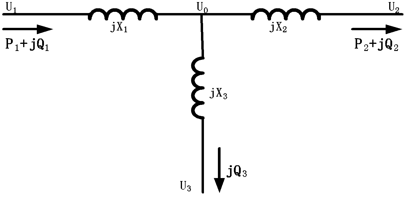
[0159] Embodiment of the relationship between the substation voltage and reactive variables in step D:
[0160] Table 1 is the grid simulation calculation results of voltage and reactive power of transformers under the condition of different active power transmission in UHV substations and the calculation results of applying expression (9), where, in expression (9), U 2 and Q 1 Using the simulation results, U 1 The calculated value of expression (9) is compared with the simulation calculated results. It can be seen from the table that when the transformer load is large, ignoring the influence of active power will cause a certain deviation in the calculation result of expression (9); using the coefficient K correction can make the calculation result closer to the program simulation result.
[0161] Table 1 Comparison of calculation results of substation voltage and reactive power formulas with simulation results
[0162]
[0163] In the embodiment, according to the above ...
Embodiment 2
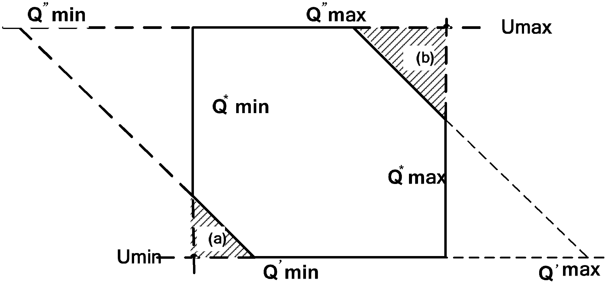
[0168] Embodiment of the judgment value range of the voltage and reactive power control strategy of the substation in step E:
[0169] In the embodiment, the voltage control ranges of the high-voltage side and the medium-voltage side of the substation are stipulated as follows during power grid operation:
[0170] High voltage side U 1 : 0.952p.u.~1.029p.u.
[0171] Medium pressure side U 2 : 0.971p.u.~0.996p.u.
[0172] Reactive power Q is obtained from expressions (10)~(13) 1 The control range of is shown in Table 3:
[0173] Table 3 Calculation results of reactive power control threshold in substation
[0174]
[0175] In the embodiment, the control requirements of reactive power stratification and partition are not proposed, so it is not considered with control threshold.
[0176] According to the simulation calculation results, it is determined that the low-voltage reactive power compensation equipment switching 1 group causes the voltage and reactive power o...
Embodiment 3
[0182] Embodiment of substation voltage and reactive power control strategy in step F:
[0183] Table 4 shows the simulation calculation results for verifying the voltage and reactive power control strategy in the thirteen-area diagram of the present invention by performing the switching operation of the low-voltage reactive power compensation equipment of the UHV substation under different voltage and reactive power conditions. The simulation calculation results show that the voltage and reactive power control strategy of the thirteen-area diagram in the present invention can accurately adjust the voltage and reactive power of the substation within the control range, and avoid repeated switching of reactive power compensation equipment.
[0184] Table 4 Simulation calculation results of substation voltage and reactive power control strategy
[0185]
[0186] The method for controlling the voltage and reactive power variable of a high-voltage power grid substation provided ...
PUM
 Abstract
Description
Claims
Application Information
 - Generate Ideas
- Intellectual Property
- Life Sciences
- Materials
- Tech Scout
- Unparalleled Data Quality
- Higher Quality Content
- 60% Fewer Hallucinations
Browse by: Latest US Patents, China's latest patents, Technical Efficacy Thesaurus, Application Domain, Technology Topic, Popular Technical Reports.
© 2025 PatSnap. All rights reserved.Legal|Privacy policy|Modern Slavery Act Transparency Statement|Sitemap|About US| Contact US: help@patsnap.com


