Large-capacity multi-functional optical fiber distribution box

A fiber optic distribution box and multi-functional technology, applied in the direction of fiber mechanical structure, can solve the problems of increasing the cost of network engineering construction, management and maintenance, etc., and achieve the effect of clear area division, convenient installation and disassembly, and convenient operation

Inactive Publication Date: 2012-07-18
CHINA TELECOM CORP LTD +1
View PDF3 Cites 7 Cited by
  • Summary
  • Abstract
  • Description
  • Claims
  • Application Information

AI Technical Summary

Problems solved by technology

[0002]In recent years, FTTH (Fiber To The Home) has been vigorously developed in my country. Due to the diversification of FTTH optical network access modes and the different environments , the requirements for optical fiber accessories are also different, so it is necessary to design wiring products with different functions to meet the needs of modern networks; this will greatly increase the cost of network engineering construction, management and maintenance

Method used


Image

  • Large-capacity multi-functional optical fiber distribution box
  • Large-capacity multi-functional optical fiber distribution box
  • Large-capacity multi-functional optical fiber distribution box

Examples


Embodiment 1

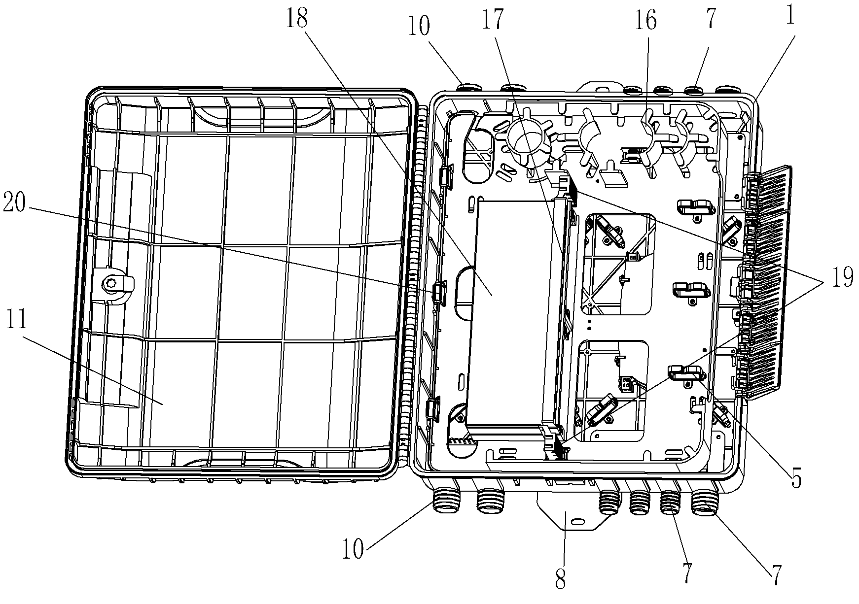
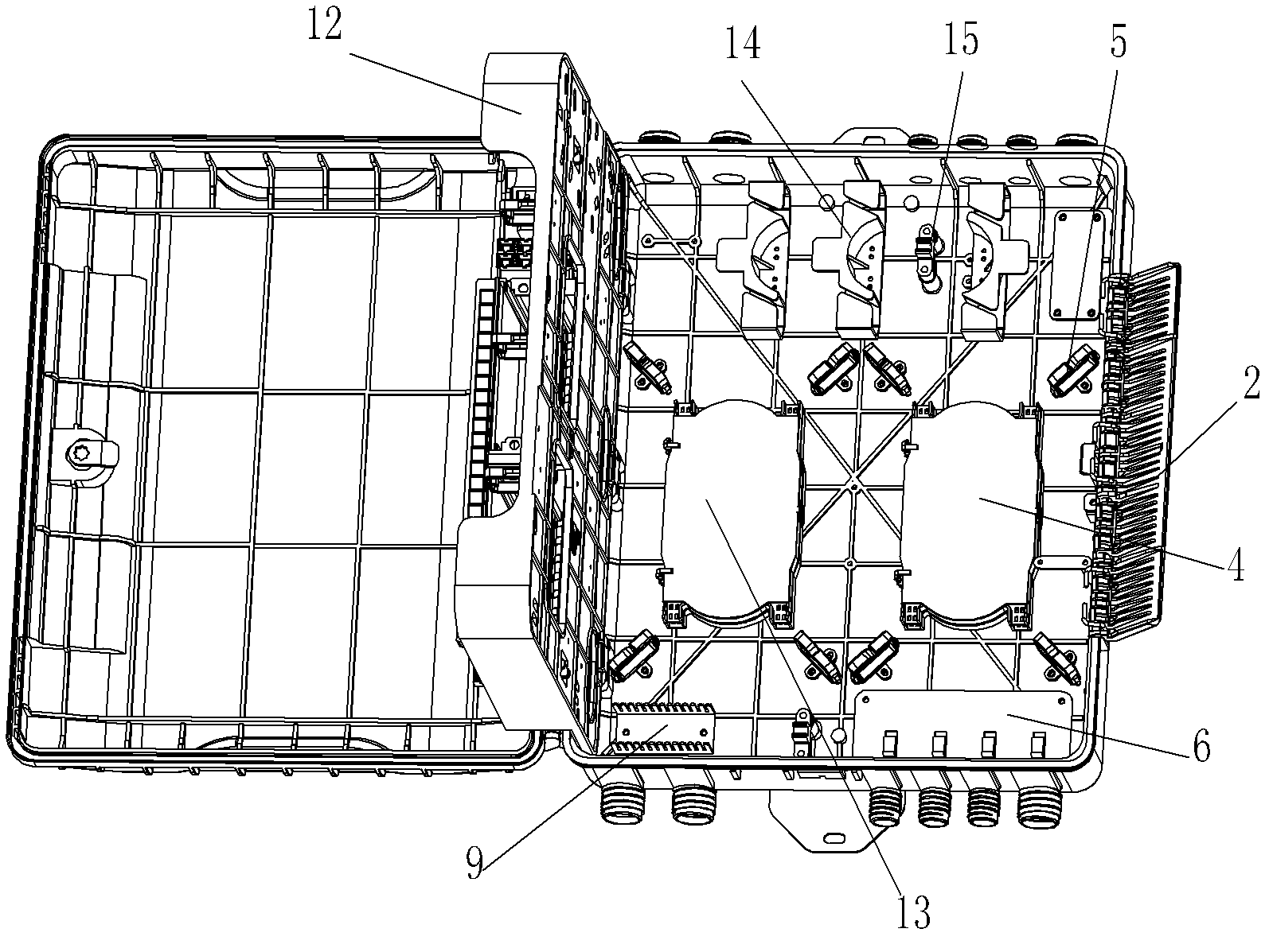
[0023] Such as figure 2 As shown, the large-capacity multifunctional optical fiber distribution box of the present invention includes a box body 1 with a cavity and a box door 11 installed on the box body. A main rotating plate 12 for separating the space of the box into inner and outer layers is hinged in the box through a buckle hinge shaft 20 (conventional parts), and the main rotating plate is fixed by a rotating plate arranged on the bottom plate of the box. Buckle 15 is fixed. The box walls on the upper and lower sides of the box body are respectively made with four optical cable inlet and outlet holes 7 (the optical cable inlet and outlet holes on the upper and lower side walls are arranged symmetrically) and two leather cable outlet holes 10 (direction refers to figure 2 ). The bottom plate of the box is provided with the main splicing tray 4 (a conventional component for optical fiber thermal fusion) and the wiring splicing tray 13 (the two splicing trays are loca...

Embodiment 2

[0030] The structure of embodiment 2 is different from embodiment 1 in that: the optical splitter mounting frame 18 on the main rotating plate is replaced with an adapter mounting seat plate 21 . Such as Figure 5 As shown, two adapter seat plates 21 (conventional structure) for installing FC-type and SC-type adapters are installed on the side of the main rotating plate close to the box door, and three transition wire rings 5 ​​are respectively arranged on the left and right sides.

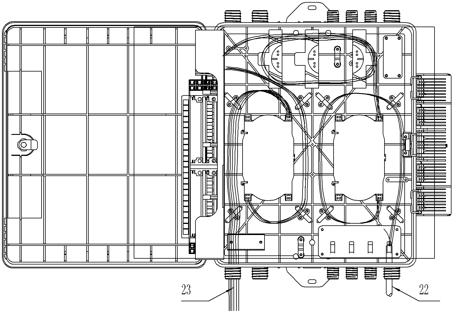
[0031] This embodiment 2 is mainly used as an end-type optical fiber distribution box , It works as Figure 7 and Figure 8 Shown:

[0032] The fiber routing of the end-type optical fiber distribution box is the same as that of the optical fiber distribution box. The left side of the adapter is terminated on the adapter through the transition line ring, and the cable pigtail is terminated on the right side at the same time. After being accommodated in the pigtail receiving area 16 of the outer...


PUM


Abstract

The invention relates to an optical fiber distribution box, and aims to ensure that the provided optical fiber distribution box is suitable for multiple connection modes, and has the characteristics of high generality and interchangeability, simple structure and low cost. The technical scheme is that the large-capacity multi-functional optical fiber distribution box is characterized by comprising a box body and a box door; each of the box walls of the upper and lower sides of the box body is provided with at least one optical cable inlet and outlet hole and at least one sheathed cable outlet; at least one fusion splice protector for splicing a fiber core is arranged at the central position of a bottom plate of the box body; a plurality of transition line ring for accommodating the optical cable is arranged around each fusion splice protector; the bottom plate of the box body is also provided with at least one sheathed cable clamp seat for fixing the sheathed cable and at least one optical fiber peeling fixing plate for fixing a peeled optical fiber; and the side wall of the box body is provided with at least one large button for fastening the box door.

Description

Technical field [0001] The invention involves a type of optical connection box, especially a fiber fiber wiring box, which is used for links and scheduling in the optical fiber communication link in different access modes.Continue. Background technique [0002] In recent years, FTTH (Fiber TO THE Home) has developed vigorously in my country. Due to the diversification and environment of FTTH optical network access mode, the requirements for optical fiber accessories are also different. Therefore Functional wiring products can adapt to the needs of modern networks; this greatly improves the cost of network engineering construction, management and maintenance.Therefore, the current optical fiber network construction puts forward the following requirements for fiber accessories: 1. In different access modes, the product should be flexible and universal; 2. The product should be clear in the core management of the core;Reduce the cost of early construction and subsequent maintenance ...

Claims


Application Information

Patent Timeline
IPC IPC(8): G02B6/44
Inventor 黄晓庆吴贞饶少勇罗序晖黄延坚帅光举
Owner CHINA TELECOM CORP LTD
Why Eureka
Try Eureka