Front-end high-power output structure for engine

An output structure and engine technology, applied in the direction of machine/engine, mechanical equipment, etc., to ensure normal operation, good reliability, simple and reliable structure

Inactive Publication Date: 2012-07-18
GUANGXI YUCHAI MASCH CO LTD
View PDF8 Cites 2 Cited by
  • Summary
  • Abstract
  • Description
  • Claims
  • Application Information

AI Technical Summary

Problems solved by technology

In order to reduce costs, this type of gearbox has been developed in China. However, since a large torque is required to drive a high-power hydraulic lift pump, the domestic gearbox cannot meet the needs of installing a high-power hydraulic lift pump. Therefore, if you want to use it in agricultural machinery Install a high-power hydraulic lift pump on the machine, only the imported gearbox can be used, and the high-power hydraulic lift pump should be installed on the imported gearbox

Method used


Image

  • Front-end high-power output structure for engine
  • Front-end high-power output structure for engine
  • Front-end high-power output structure for engine

Examples


Embodiment Construction

[0025] In order to further illustrate the structure and function of the present invention, the present invention will be described in detail below in conjunction with the accompanying drawings and preferred embodiments, but it should be understood that the protection scope of the present invention is not limited by specific embodiments.

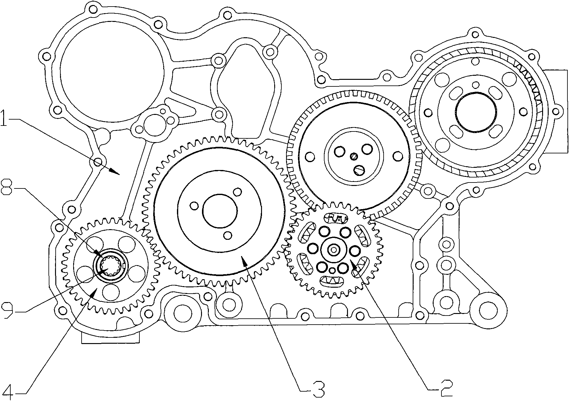
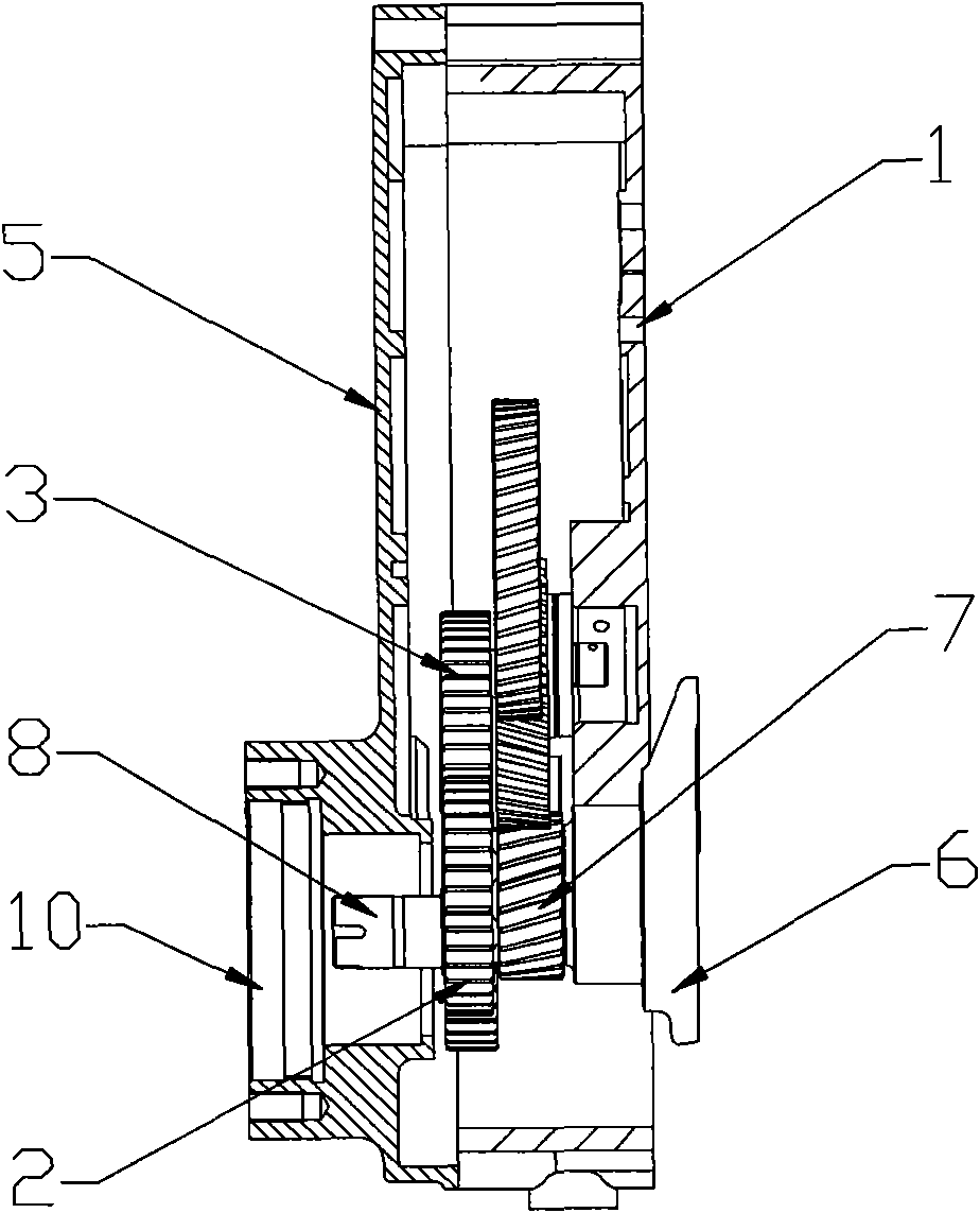
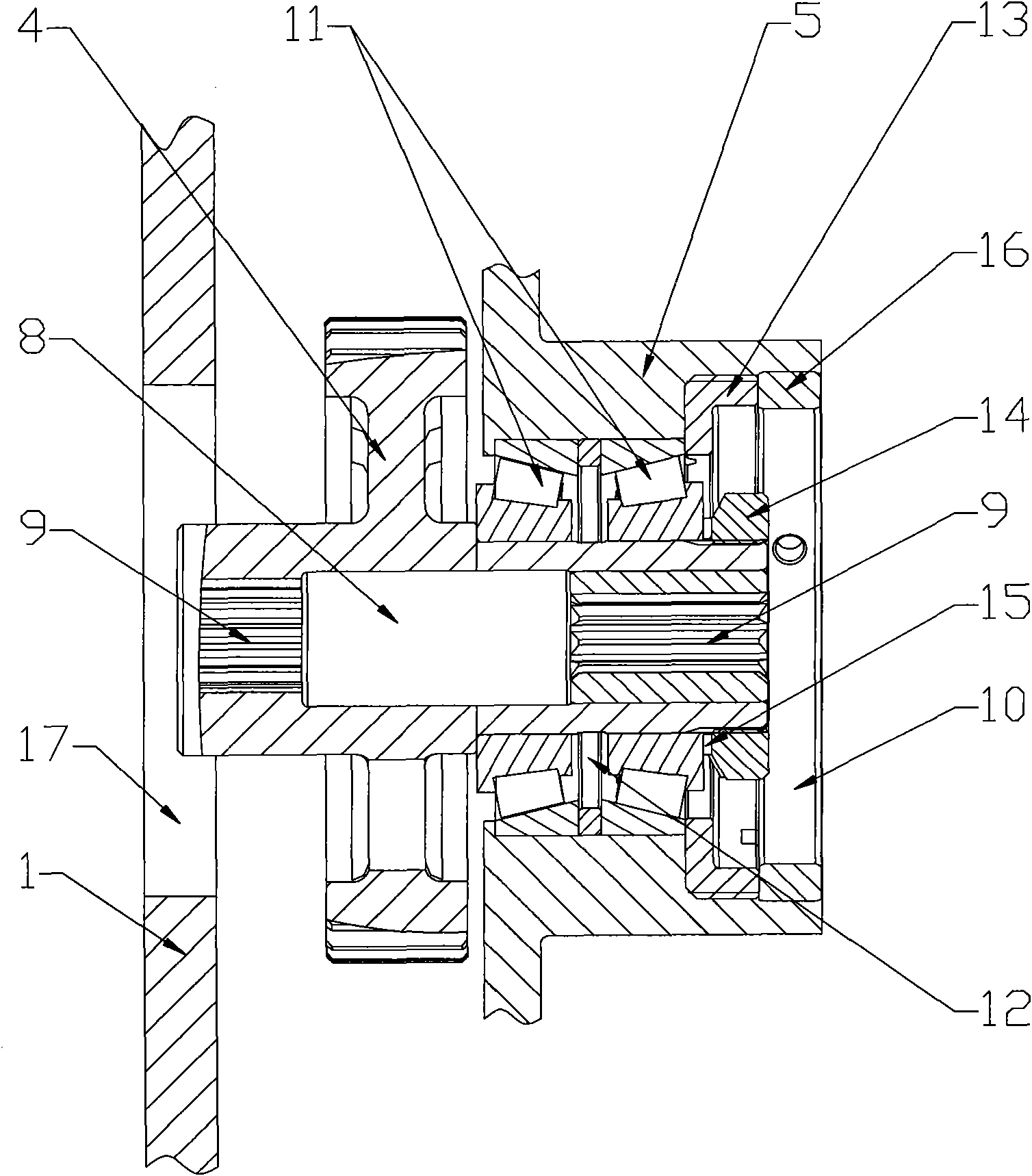
[0026] The invention is a high power output structure at the front end of the engine, figure 1 It is a schematic diagram of the distribution of the gear set in the gear chamber 1 of the present invention. As shown in the figure, the gear set is composed of a transmission gear 2, an idler gear 3 and a power output gear 4. The transmission gear 2 meshes with the idler gear 3. The idler gear The gear 3 is unilaterally supported by a sliding bearing and connected to the gear chamber 1, and the idler gear 3 meshes with the power output gear 4. The power output gear 4 is an integral structure of a gear and a transmission shaft 8. The two ends of the...


PUM


Abstract

The invention discloses a front-end high-power output structure for an engine, which is characterized by comprising a gear set arranged in an engine gear chamber. The gear set comprises a transmission gear, an idle gear and a power output gear, the transmission gear is coaxially and fixedly connected with a crankshaft timing gear and meshed with the idle gear, the idle gear is unilaterally supported and connected onto the gear chamber and meshed with the power output gear, and the power output gear is provided with an output device for outputting power. By means of a front-end gear train which is arranged on the engine gear chamber and used for front-end power output, the output power can reach more than 60KW, and the requirement of mounting a high-power hydraulic lifting pump can be met while the structure is reliable and an output interface position is arranged flexibly.

Description

technical field [0001] The invention relates to the technical field of engine machinery, and more specifically relates to a high-power output structure at the front end of the engine. Background technique [0002] Some agricultural machinery, such as tractors, often need to perform lifting and steering actions of large farm implements when performing operations. This action is generally completed by a high-power hydraulic lift pump. The current status quo is that this kind of high-power hydraulic lift pump is installed on the gearbox, but this kind of gearbox is basically imported, and the cost is very high. In order to reduce costs, this type of gearbox has been developed in China. However, since a large torque is required to drive a high-power hydraulic lift pump, the domestic gearbox cannot meet the needs of installing a high-power hydraulic lift pump. Therefore, if you want to use it in agricultural machinery To install a high-power hydraulic lift pump on the machine, o...

Claims


Application Information

Patent Timeline
IPC IPC(8): F02B61/06
Inventor 曹杨军陈剑涛王宏伟
Owner GUANGXI YUCHAI MASCH CO LTD
Why Eureka
Try Eureka