
Electric spinning machine

An electrospinning machine and electrospinning technology, applied in textiles and papermaking, fiber processing, filament/thread forming, etc., can solve problems such as volatile solutions and poor continuity of spun fibers

Active Publication Date: 2012-07-18
MEDPRIN REGENERATIVE MEDICAL TECH +1
View PDF1 Cites 13 Cited by
  • Summary
  • Abstract
  • Description
  • Claims
  • Application Information

AI Technical Summary

Problems solved by technology

With this structure, the continuity of spinning fibers is not as good as that of capillary electrospinning equipment; the solution is in a relatively open environment, and the solution is volatile

Method used


Image

  • Electric spinning machine
  • Electric spinning machine
  • Electric spinning machine

Examples


Embodiment 1

[0034] The electrospinning machine includes an electrospinning solution supply device, an electrospinning solution spinning device, a receiving device and a high-voltage electrostatic generator. Such as figure 1 As shown, the receiving device includes four receiving rollers 1 , and the receiving rollers 1 are all mounted on a support frame 2 . Along the axial direction of the receiving rollers 1, two receiving rollers 1 are arranged in a row; along the parallel direction of the receiving rollers 1, the receiving rollers 1 are arranged in two rows. A row of receiving rollers 1 is a group, and the receiving rollers 1 of the same group are driven by gears and rotated by motors; the two receiving rollers 1 of the same group rotate at the same speed, and the speed can be adjusted at the same time. The spray head 3 is arranged directly above the receiving roller 1 , and the four receiving rollers 1 correspond to the four spray heads 3 , and the spray head 3 is installed on the brac...

Embodiment 2

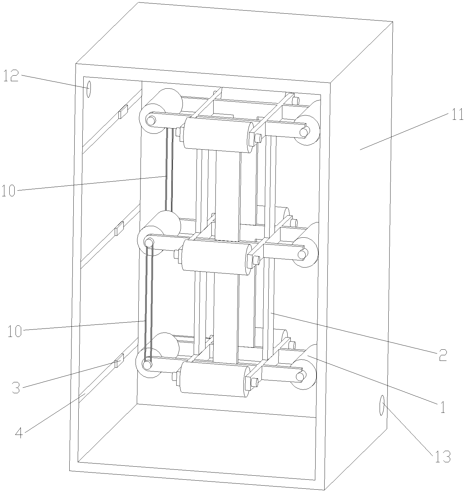
[0039] The electrospinning machine includes an electrospinning solution supply device, an electrospinning solution spinning device, a receiving device, a vacuum box 11 and a high-voltage electrostatic generator. image 3 As shown, the receiving roller 1 of the receiving device has a multi-layer ring structure. Twelve receiving rollers 1 are arranged in three layers, four in each layer form a circle, and corresponding vertical receiving rollers 1 between different horizontal planes are parallel to each other. Three parallel receiving rollers 1 in a vertical row form a group, driven by a motor, and the adjacent receiving rollers 1 are driven by a belt 10, so that the same group of receiving rollers 1 rotate and receive at the same speed, and the speed can be adjusted at the same time.

[0040] The outside of each receiving roller 1 is provided with a spray nozzle 3 ( image 3 Not all twelve nozzles are shown). The spray head 3 reciprocates along the axial direction of the rece...


PUM

PropertyMeasurementUnit
lengthaaaaaaaaaa

Abstract

The invention relates to an electric spinning machine, comprising a multi-roller receiving device, a spinning spray head and a vacuum box body. The multi-roller receiving device comprises a plurality of rotary planar rollers and a plurality of tridimensional rollers; an electric spinning liquid spinning device comprises a spray head and an electric spinning liquid supply device, the spray head comprises a needle and a liquid storage container with a through hole; the electric spinning liquid flows out from a gap between the needle and the through hole, the electric spinning liquid forms into Taylor cones through the spray head, and filaments are discharged and are conveyed to more than two receiving rollers; each receiving roller corresponds to at least one spray head, and the spray head does reciprocating motion along the axial direction of the corresponding receiving roller; and the electric spinning liquid spinning device and the receiving device are contained in the vacuum box body, the air is processed after leaving the vacuum box through the extract opening, of the vacuum box, and then the air returns to the vacuum box through the air inlet of the vacuum box to perform next circulation. The electric spinning machine has the advantages of simple structure and can effectively improve the production efficiency, so that the electric spinning machine is suitable for application in the static spinning field.

Description

technical field [0001] The invention relates to electrospinning technology, in particular to an electrospinning device suitable for the preparation of nanofiber materials. Background technique [0002] In the preparation method of nanofibrous materials, electrospinning technology has unique advantages. First of all, the ultrafine fibers prepared by the conventional spinning industry can only reach the micron level, which cannot meet the requirements of fine filtration, porous scaffolds and many other applications. For example, in the field of tissue engineering scaffolds, fibers with small diameters are required to facilitate the degradation of the body absorb. The diameter of the fiber prepared by electrospinning in the application is 100 to 500 nm, which can better meet the requirements of the application. Secondly, electrospinning has been recognized as the simplest and most effective method for preparing nanofibers and has been successfully used in the preparation of n...

Claims


Application Information

Patent Timeline
Patent Type & Authority Applications(China)
IPC IPC(8): D01D5/00
Inventor 王国帅徐弢袁玉宇
Owner MEDPRIN REGENERATIVE MEDICAL TECH
Learn More