
Method and device for checking scales of resistivity logging instrument

A technology of resistivity logging and calibration method, which is applied in the field of petroleum drilling engineering, and can solve the problems of complex antenna structure and electronic circuit, increasing the unreliability of instruments, etc.

Active Publication Date: 2012-07-11
BC P INC CHINA NAT PETROLEUM CORP +1
View PDF5 Cites 37 Cited by
  • Summary
  • Abstract
  • Description
  • Claims
  • Application Information

AI Technical Summary

Problems solved by technology

In this method, the scale antenna and the receiving wire are installed together, and the scale and measurement are switched alternately, which makes the antenna structure and electronic circuit complicated, and increases the unreliability of the instrument
[0006] U.S. Patent No.5293128 proposes a conductive ring calibration device similar to a wireline induction logging tool. Electronic components with different impedances are connected to the conductive ring to simulate formations with different resistivities. This conductive ring calibration method is not suitable for Electromagnetic wave resistivity logging tool while drilling

Method used


Image

  • Method and device for checking scales of resistivity logging instrument
  • Method and device for checking scales of resistivity logging instrument
  • Method and device for checking scales of resistivity logging instrument

Examples


Embodiment Construction

[0027] In order to make the purpose, technical solutions and advantages of the embodiments of the present invention more clear, the embodiments of the present invention will be further described in detail below in conjunction with the accompanying drawings. Here, the exemplary embodiments and descriptions of the present invention are used to explain the present invention, but not to limit the present invention.

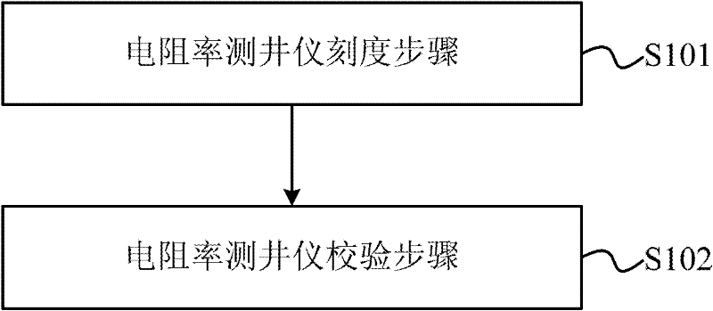
[0028] Such as figure 1 As shown, the present embodiment provides a method for calibration calibration of a resistivity logging tool, the method comprising:

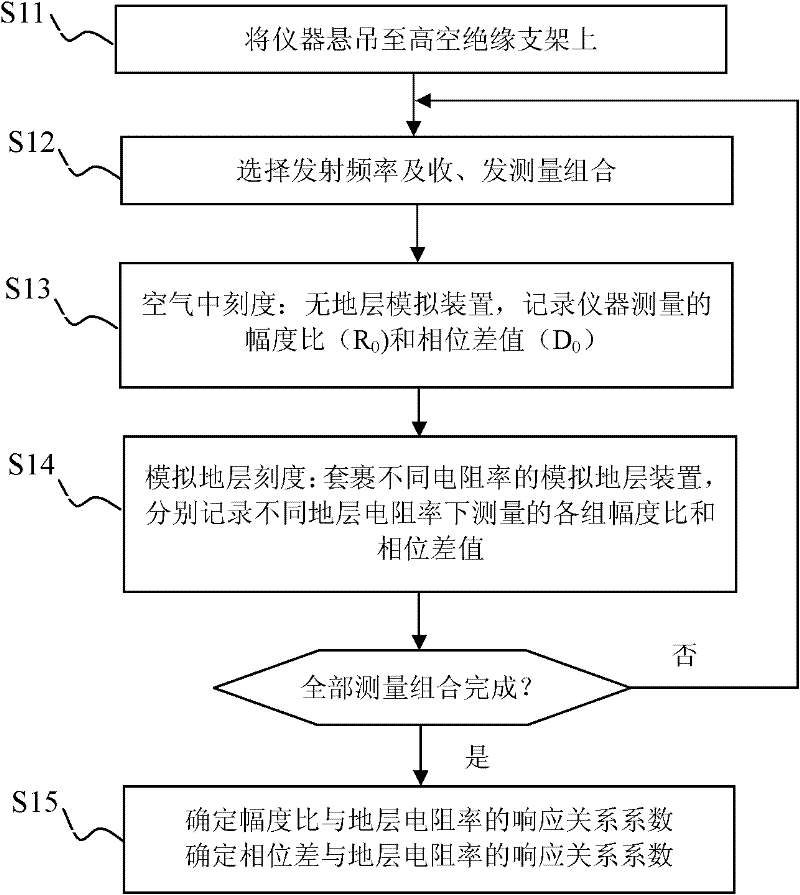
[0029] S101: Resistivity logging tool calibration step: measure the amplitude ratio R of the signal when the resistivity logging tool is exposed to air 0 and phase difference D 0 and the amplitude ratio R of the signal when simulated formations with different resistivities are placed around the resistivity logging tool n and phase difference D n ;according to R 0 、D 0 , R n and D n Determine the amplitud...


PUM


Abstract

The invention discloses a method and device for checking scales of a resistivity logging instrument, and the method comprises a resistivity logging instrument calibrating step and a resistivity logging instrument checking step, wherein the resistivity logging instrument calibrating step is as follows: measuring the amplitude ratio R0 and the phase difference D0 of signals when the resistivity logging instrument is exposed in air, measuring the amplitude ratio Rn and the phase difference Dn of the signals when simulated formations with different resistivities are placed around the resistivity logging instrument, and confirming the amplitude ratio response function relationship and the phase difference response function relationship according to R0, D0, Rn and Dn; and the resistivity logging instrument checking step is as follows: measuring the amplitude ratio R and the phase difference D of the signals when a simulated formation with resistivity Rho is placed nearby the logging instrument, calculating the amplitude ratio resistivity and the phase difference resistivity as per R, D, the amplitude response function relationship and the phase difference response function relationship, and calculating difference values of the amplitude ratio resistivity and the phase difference resistivity with the resistivity Rho. If the difference values of the amplitude ratio resistivity and the phase difference resistivity with the resistivity Rho are both less than a preset measuring error of the instrument, the resistivity logging instrument passes through the checking.

Description

technical field [0001] The present invention relates to oil drilling engineering technology, in particular to electromagnetic wave resistivity measurement technology while drilling, in particular to a calibration calibration method and device of resistivity logging instrument. Background technique [0002] During the exploration and development of oil, natural gas and unconventional oil and gas resources, the steerable drilling system measures the resistivity parameters of the drilled formation in real time, which not only provides useful steering information for the drilling system, but also provides indispensable geological data for real-time comprehensive evaluation of the formation. parameter. The electromagnetic wave resistivity measurement technology while drilling utilizes the principle of electromagnetic wave propagation in the medium, transmits electromagnetic waves of different frequencies to the formation through multiple sets of transmitting antennas, and simulta...

Claims


Application Information

Patent Timeline
IPC IPC(8): G01V13/00
Inventor 宋延淳艾维平邓乐窦修荣贾衡天
Owner BC P INC CHINA NAT PETROLEUM CORP
Learn More