
Boom device and concrete pump truck

A technology for concrete pump trucks and booms, which is applied in hoisting devices, transportation and packaging, and processing of building materials, etc. It can solve the problems of unsatisfactory layout of super-long booms, limited layout space, and limited increase in the number of boom sections, etc. question

Active Publication Date: 2012-07-11
SANY HEAVY IND CO LTD (CN)
View PDF7 Cites 5 Cited by
  • Summary
  • Abstract
  • Description
  • Claims
  • Application Information

AI Technical Summary

Problems solved by technology

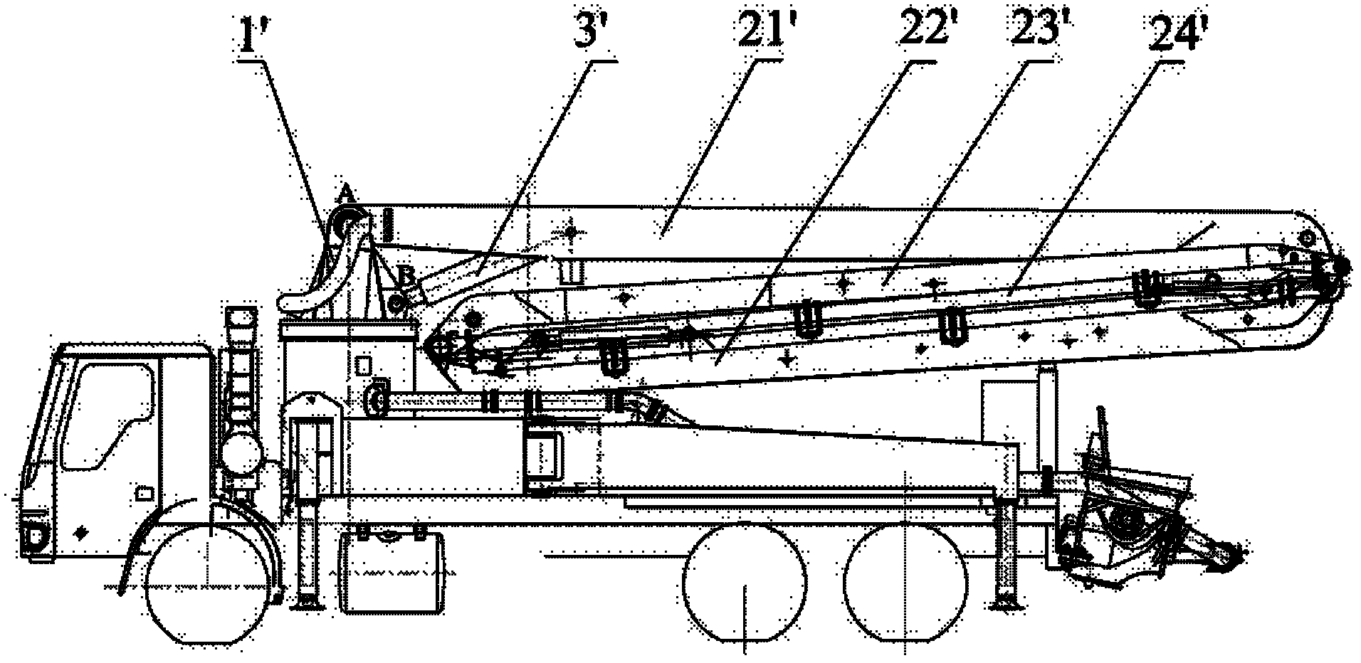
Therefore, in this type of boom arrangement, the length of each section of the boom is limited, and in order to increase the deployment length of the boom device, it is necessary to increase the number of sections of the boom; however, due to the arrangement below the first boom 21' The space is limited, and the increase in the number of jib sections is limited
[0007] Under the current development trend of concrete pump trucks towards ultra-high pumping height and ultra-wide distribution range, the arrangement of booms in the prior art cannot satisfy the arrangement of ultra-long booms

Method used


Image

  • Boom device and concrete pump truck
  • Boom device and concrete pump truck
  • Boom device and concrete pump truck

Examples


Embodiment Construction

[0036] In order to enable those skilled in the art to better understand the technical solutions of the present invention, the present invention will be further described in detail below in conjunction with the accompanying drawings and specific embodiments.

[0037] Please see figure 2 , image 3 , Figure 4 , figure 2 Schematic diagram of the structure of the boom device provided for a specific embodiment of the present invention; image 3 for figure 2 Schematic diagram of the layout of the transfer platform and the first jib; Figure 4 for image 3 Schematic diagram of the arrangement of the first section jib and the second section jib.

[0038] Such as figure 2 , image 3 , Figure 4As shown, the present invention provides a kind of arm frame device, is used for construction machine, and this arm frame device comprises the multi-section arm frame that hinges in sequence, and turntable 2 is arranged on the chassis and is positioned at the middle part of construc...


PUM


Abstract

The invention discloses a boom device, which comprises a plurality of boom segments hinged in sequence. The first boom segment is hinged to a rotary table of an engineering machine, the rotary table is disposed in the middle of the engineering machine, the first boom segment is disposed upside down, the second boom segment is hinged to the first boom segment and folded above the first boom segment, and all of from the second boom segment to the final boom segment penetrates through a body of the engineering machine. The rotary table is disposed in the middle of the engineering machine, the first boom segment is disposed upside down and extends towards the tail of the engineering machine or towards a cab of the engineering machine, all of from the second boom segment to the final boom segment can penetrate through the body of the whole engineering machine, namely penetrating from the cab of the engineering machine to the tail thereof lengthwise along the engineering machine, and accordingly, arrangement of an ultra-long boom can be achieved, extension height of the whole boom device is further increased so as to extend the distribution range of the boom device. The invention further provides a concrete pump truck.

Description

technical field [0001] The invention relates to the technical field of concrete pumping, in particular to an arm support device. The present invention also relates to a concrete pump truck with the above boom device. Background technique [0002] With the rapid development of my country's economic construction, the market demand for construction machinery, especially concrete pump trucks, is increasing. [0003] The boom in the concrete pump truck is generally multi-section, and each section of the boom can be folded. During the working process of the concrete pump truck, the concrete needs to be transported to the designated position through the delivery pipe fixed on the boom, and as the delivery position changes, the boom needs to drive the delivery pipe to realize unfolding, folding and rotation. [0004] Such as figure 1 Shown is a schematic diagram of the structure of a typical concrete pump truck. The boom device of the concrete pump truck includes a turntable 1',...

Claims


Application Information

Patent Timeline
IPC IPC(8): E04G21/04
CPCE04G21/0445E04G21/0436E04G21/04B66C23/54
Inventor 谢世惠邓彪吴永红
Owner SANY HEAVY IND CO LTD (CN)
Learn More