
Novel right-angled carrying manipulator

A manipulator, right-angle technology, applied in the direction of conveyor objects, transportation and packaging, which can solve problems such as unreachable, high speed, etc.

Inactive Publication Date: 2012-07-11
邹建炀 +1
View PDF4 Cites 25 Cited by
  • Summary
  • Abstract
  • Description
  • Claims
  • Application Information

AI Technical Summary

Problems solved by technology

And because the cylinder must switch the direction of the compressed air through the solenoid valve to achieve the extension, retraction or rotation of the cylinder, this kind of handling device cannot reach a higher speed

Method used


Image

  • Novel right-angled carrying manipulator
  • Novel right-angled carrying manipulator
  • Novel right-angled carrying manipulator

Examples


Embodiment Construction

[0014] The specific embodiments of the present invention will be further described below with reference to the accompanying drawings.

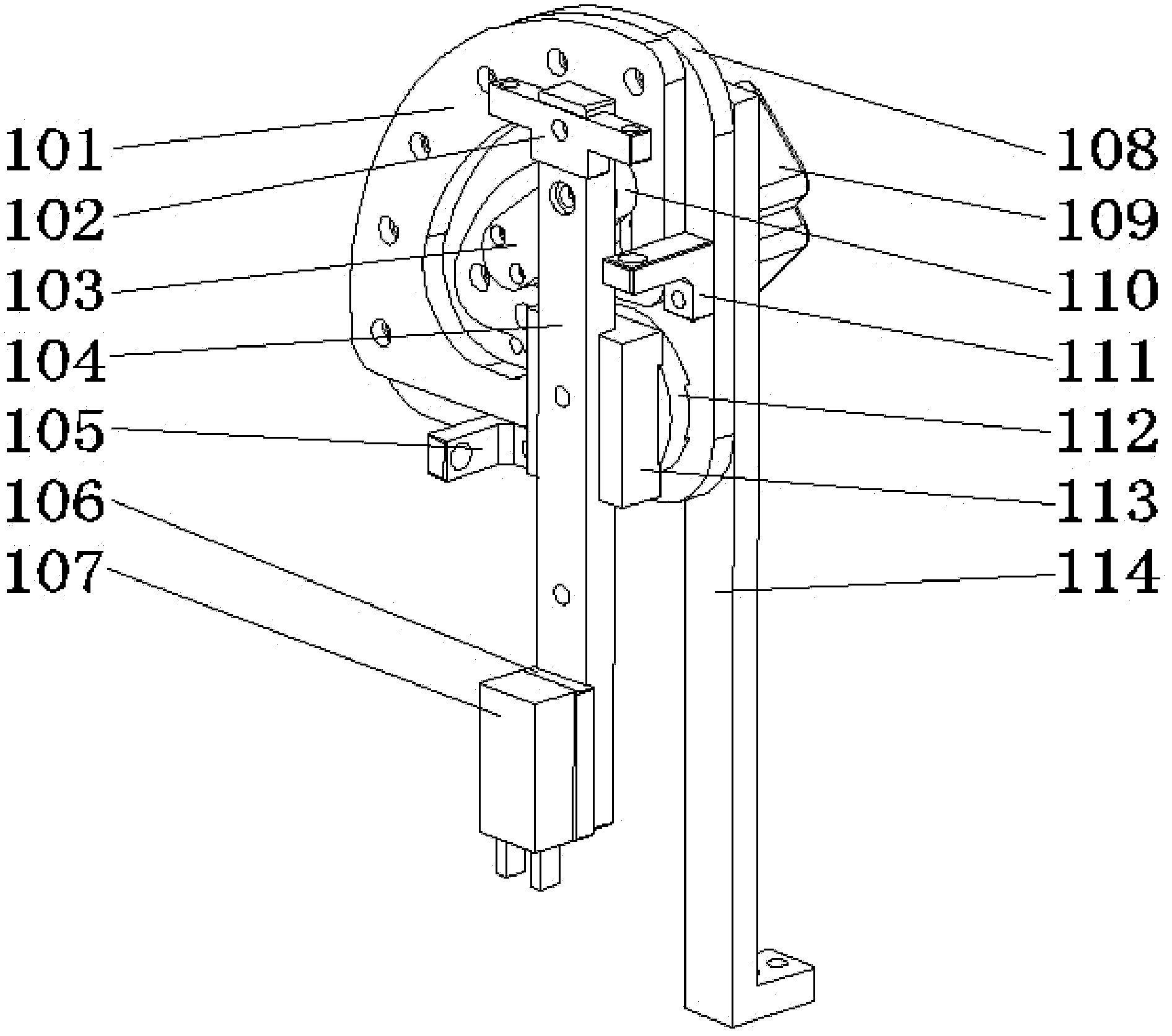
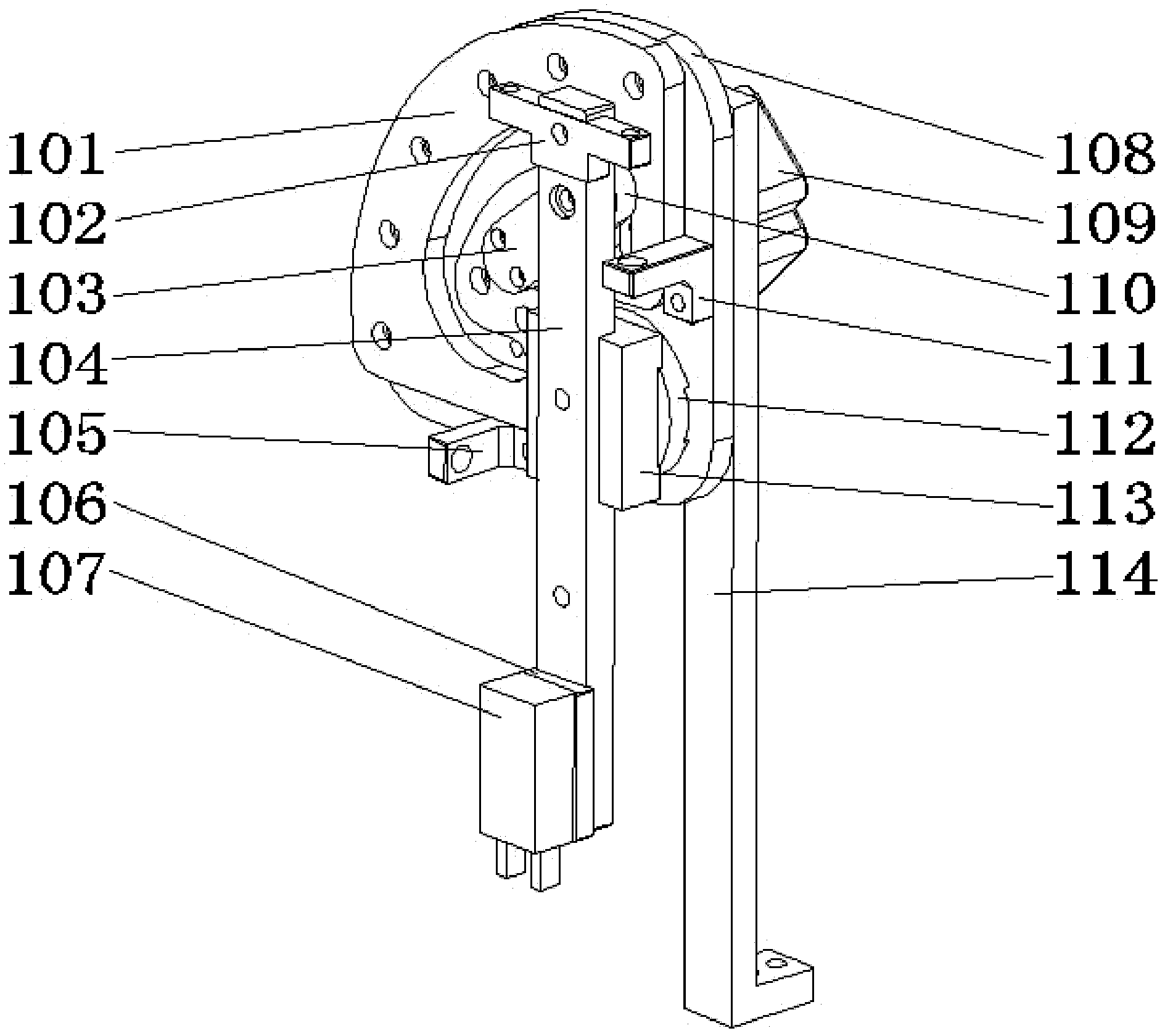
[0015] The novel right-angle handling manipulator of the present invention is as follows: figure 1 As shown, it includes the manipulator body, which is mainly composed of a track rest template 101, a limit stop block 102, a cam follower fixing plate 103, a linear slider 104, a left limit block 105, a clamping cylinder 107, and clamping cylinder mounting plate 106 , Manipulator fixed plate 108, stepping motor (stepping motor) 109, cam follower 110, right limit block 111, bearing seat 112, slide rail 113, support plate 114 and other components.

[0016] The manipulator body is mounted and fixed on the production line by the support plate 114 . The manipulator fixing plate 108 is located on the upper part of the support plate 114. Of course, the manipulator fixing plate 108 and the support plate 114 may be integrated or combined, which constitut...


PUM


Abstract

The invention discloses a novel right-angled carrying manipulator comprising a manipulator support fixed on a production line, wherein the right lower side of the manipulator support is connected with a sliding rail and a linear slide block sliding back and forth along the sliding rail through bearings, the bottom of the linear slide block is provided with a clamping cylinder, and the top of the linear slide block is connected with a C-shaped track sliding device of which an initial action point is arranged right above a bearing block and the final action point is arranged on a horizontal line of the bearing block. An output shaft of a stepping motor is used for transmitting a rotating force to a cam follower fixing plate and driving the cam follower fixing plate to rotate so that the linear slide block acts along a C-shaped track on a track master plate, the slide rail can only rotate around the bearing block; finally, the tail end of the linear slide block is converted into a marked-out right-angled track, and the action is finished from the beginning to the end without stopping; the clamping cylinder is matched for making corresponding opening and closing actions to finish the right-angled carrying of appointed articles; and the manipulator is enabled to do high-speed point-to-point reciprocated actions to meet the requirement for high-speed carrying.

Description

technical field [0001] The invention relates to a right-angle conveying manipulator, more precisely, to a device capable of picking up articles at high speed and rotating them by 90 degrees and then placing them in a designated position laterally on a production line or in an automatic assembly process. Background technique [0002] Right-angle handling robots are widely used in production assembly and automation machinery. Usually the existing right-angle handling manipulator uses a cylinder to drive a clamping mechanism on a slide rail to pick up the items to be transported longitudinally, and then uses a rotating cylinder to turn the above items and the clamping mechanism 90 degrees to complete the right-angle handling of the items action. [0003] During the handling process of the ordinary right-angle pneumatic handling manipulator, because it needs to prevent collision with other items or obstacles on the production line, after picking it up longitudinally, the cylind...

Claims


Application Information

Patent Timeline
Patent Type & Authority Applications(China)
IPC IPC(8): B65G47/91
Inventor 邹建炀李怡旸
Owner 邹建炀
Learn More