Copper wire pneumatic compression transmission device

A pneumatic compression and transmission technology, applied in the direction of electrical components, circuits, conductor/cable insulation, etc., can solve the problems of inability to ensure straight line transmission, easy twisting and deformation of copper wires, etc., achieve high efficiency, ensure quality, and fast lifting Effect

Active Publication Date: 2013-09-25
常州金方圆新材料有限公司
View PDF11 Cites 0 Cited by
  • Summary
  • Abstract
  • Description
  • Claims
  • Application Information

AI Technical Summary

Problems solved by technology

[0003] The purpose of the present invention is to provide a solution that can solve the aforementioned problems in view of the problems that the existing copper wire insulation layer winding device described in the background technology cannot guarantee straight line transmission and the copper wire is easily twisted and deformed. Copper wire pneumatic compression transmission device

Method used


Image

  • Copper wire pneumatic compression transmission device
  • Copper wire pneumatic compression transmission device
  • Copper wire pneumatic compression transmission device

Examples


Embodiment Construction

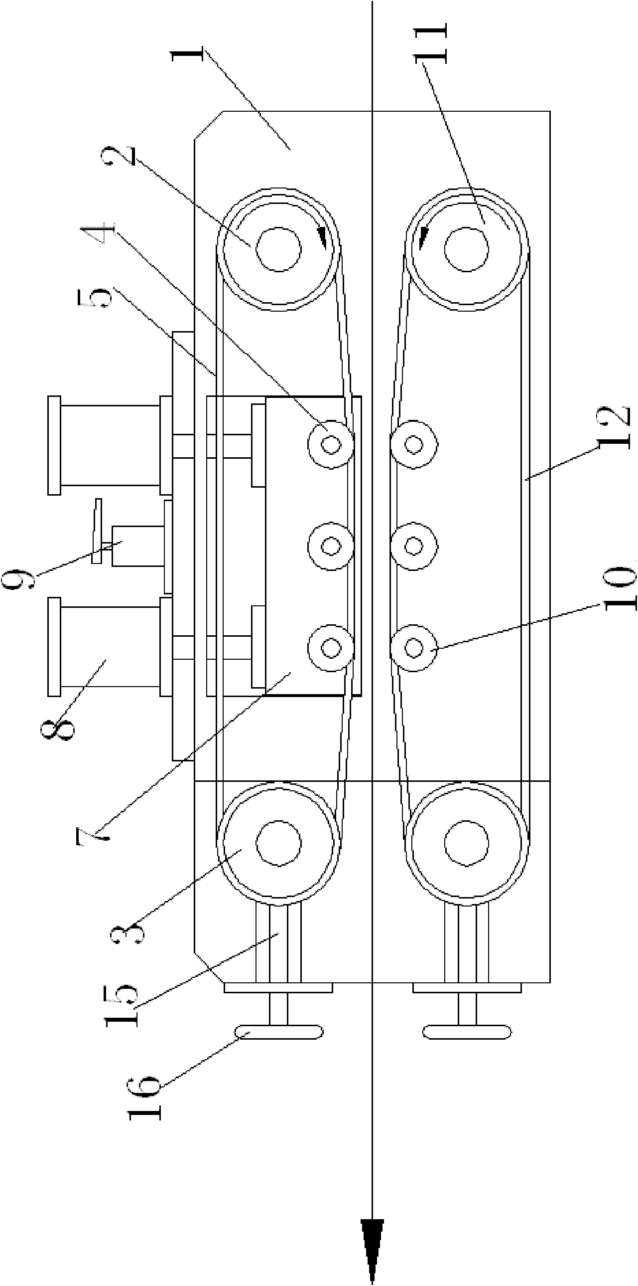
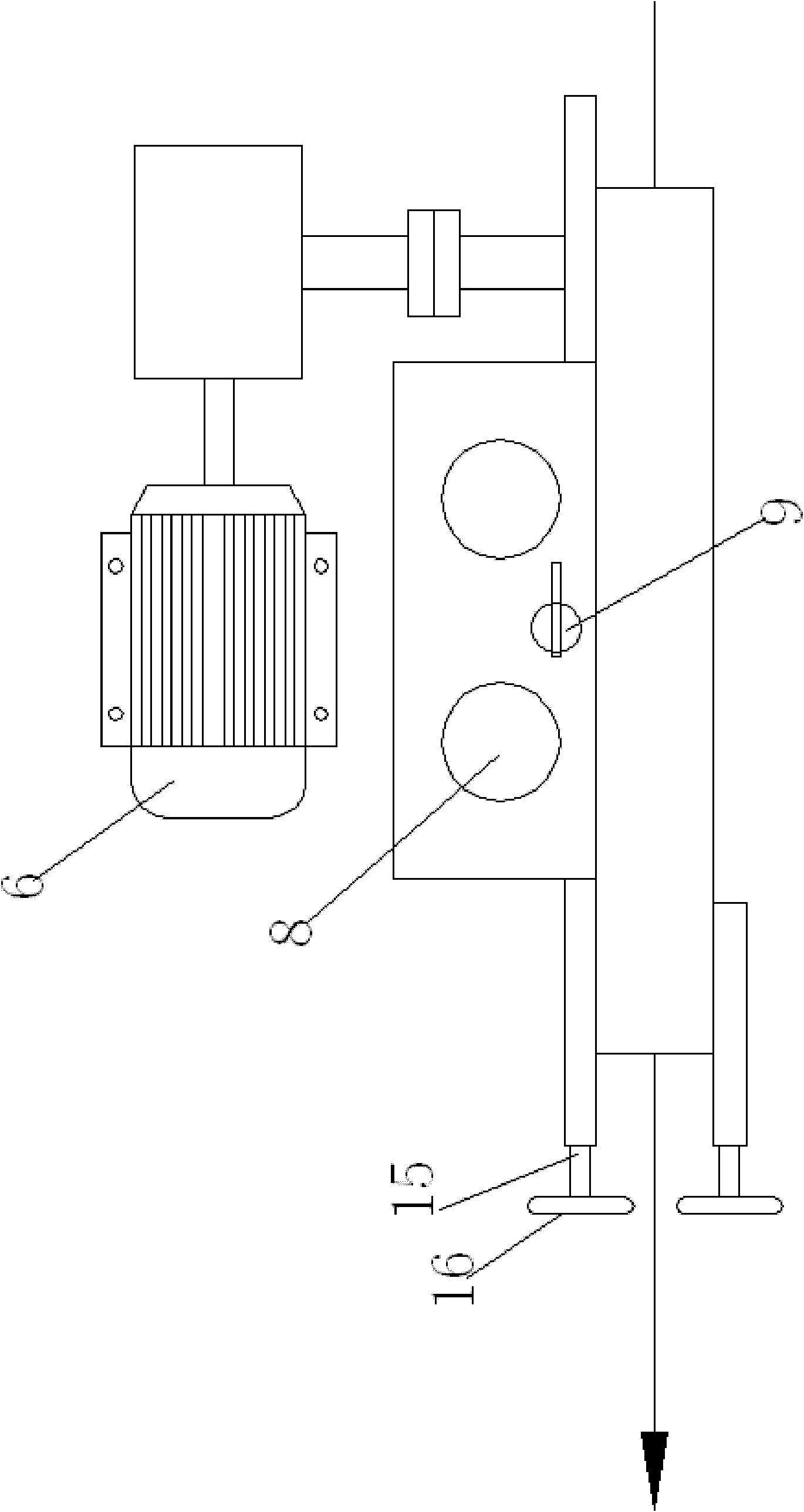
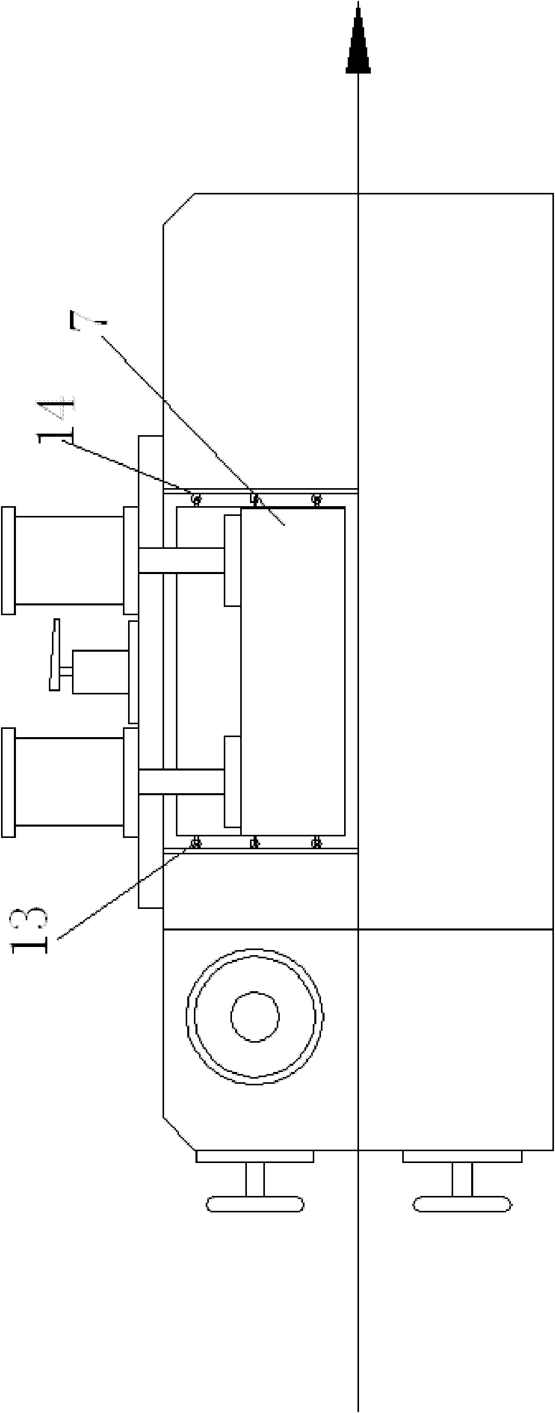
[0013] Reference Figure 1 to Figure 3 A copper wire pneumatic compression transmission device is shown, which includes a main body 1, an active synchronous belt wheel set and a passive synchronous belt wheel set arranged on the main body 1. The active synchronous belt wheel set includes an upper driving wheel 2 and an upper driven wheel 3. The upper driven wheel group 4 and the upper conveyor belt 5, the driving wheel is driven by the motor 6, the upper driven wheel group 4 is arranged on the lifting plate 7, the lifting plate 7 is connected with the push rod of the cylinder 8 arranged on the top of the main body 1, the main body 1 An air pressure adjustment switch 9 for controlling the contraction of the push rod of the cylinder 8 is provided on the upper part. The passive synchronous belt wheel group includes a lower driven wheel group 10, two lower driven wheels 11 and a lower conveyor belt 12. The lower driven wheel group 10 is fixed on the main body 1.

[0014] On the basis...


PUM


Abstract

The invention relates to a copper wire pneumatic compression transmission device which comprises a main body, a driving synchronous belt pulley group and a driven synchronous belt pulley group, wherein the driving synchronous belt pulley group and the driven synchronous belt pulley group are arranged on the main body; the driving synchronous belt pulley group comprises an upper driving pulley, an upper driven pulley, an upper driven pulley group and an upper conveying belt; the driving pulley is driven through a motor; the upper driven pulley group is arranged on a lifting plate; the lifting plate is connected with a push rod of a cylinder arranged at the top of the main body; a gas pressure regulating switch for controlling the shrinkage of the push rod of the cylinder is arranged on the main body; the driven synchronous belt pulley group comprises a lower driven pulley group, two lower driven pulleys and a lower conveying belt; and the lower driven pulley group is fixed on the main body. According to the copper wire pneumatic compression transmission device, the lifting of the upper driven pulley group is pneumatically controlled, thus the operation is simple, the lifting speed is high, the efficiency is high, and more manpower resources are saved.

Description

Technical field [0001] The invention relates to a mechanical transmission device, in particular to a copper wire transmission device used for a copper wire insulation layer winding device. Background technique [0002] In the process of copper wire processing, it is necessary to wrap an insulating layer on the surface of the bare copper wire, sinter the insulating layer, and then wind the mica layer. In this process, the copper wire needs to be pulled so that the copper wire can be oriented along a straight line. Front transmission, the copper wire transmission of the existing copper wire insulation winding device is mainly driven by the pulling force at the copper wire take-up place, because the take-up place is far away from the insulating layer winding place, and the middle needs to be sintered and baked. Baking, cooling and mica layer winding and other processes, therefore, the straight line transmission of the copper wire cannot be guaranteed, and it is easy to cause the cop...

Claims


Application Information

Patent Timeline
Patent Type & Authority Patents(China)
IPC IPC(8): H01B13/00H01B13/08H01B13/26
Inventor 芮建方
Owner 常州金方圆新材料有限公司
Why Eureka
Try Eureka