Ultrasonic detector

A detector and ultrasonic technology, which is used in the analysis of solids using sonic/ultrasonic/infrasonic waves, and can solve problems such as energy retention, large energy consumption, and probe overheating.

Inactive Publication Date: 2012-07-04
UNITED IMAGING SYST BEIJING CO LTD
View PDF5 Cites 9 Cited by
  • Summary
  • Abstract
  • Description
  • Claims
  • Application Information

AI Technical Summary

Problems solved by technology

[0004] In the state of empty working period, the work of the ultrasonic detector is ineffective, which consumes a large amount of energy needlessly, and the emitted energy stays on the surface of the probe, causing the probe to overheat

Method used


Image

  • Ultrasonic detector
  • Ultrasonic detector
  • Ultrasonic detector

Examples


Embodiment Construction

[0013] In the following detailed description, reference is made to the drawings in which parts are formed, in which like numerals refer to like parts throughout, and are shown by exemplary specific embodiments in which the invention may be practiced. It is to be understood that other embodiments may be utilized and structural or logical changes may be made without departing from the scope of the present invention. Accordingly, the following detailed description is not limiting, and the scope of the invention is defined by the appended claims and their equivalents.

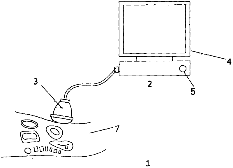
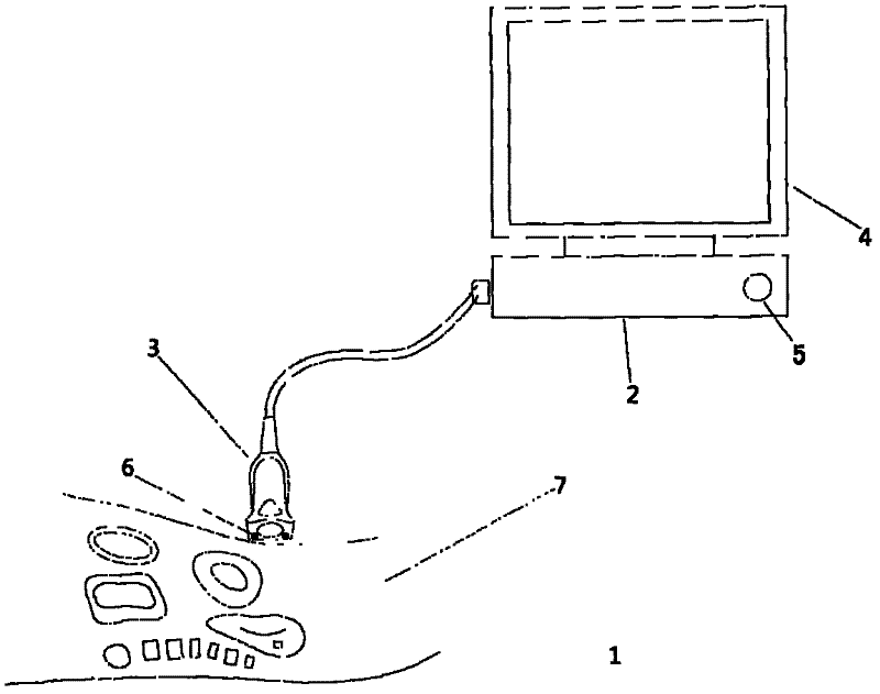
[0014] figure 1 is a diagram of a prior art ultrasonic probe. Ultrasonic detector 1 usually mainly includes host 2 and probe 3 . The host computer 2 is used to control the work of the ultrasonic detector 1 . The host 2 usually also includes a display 4 for displaying detection results.

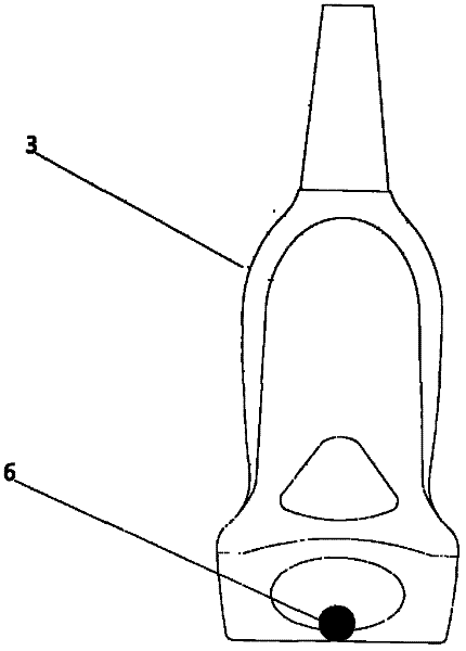
[0015] The probe 3 is provided with an acoustic transducer, which converts electrical energy into ultrasonic energy, and conv...


PUM


Abstract

The invention provides an energy-saving and safe ultrasonic detector, which comprises a main machine and a probe and is characterized by further comprising a contact sensor arranged at the position of the probe. The contact sensor is connected with the main machine and used for detecting that the probe and an object to be detected are in the contact state or non-contact state and sending the detected state of the probe to the main machine. The main machine controls states of the ultrasonic detector according to the states of the probe.

Description

technical field [0001] The present invention relates to ultrasonic instruments, and more particularly, to ultrasonic probes. Background technique [0002] Ultrasonic detectors are instruments that use ultrasonic waves to detect the internal structure of objects. Ultrasonic detectors usually mainly include a host and a probe, wherein an acoustic transducer is disposed in the probe. When working, the host controls the transducer to generate short and strong sound pulses to create sound waves. When the sound wave encounters an object with different acoustic impedance, part of the sound wave will be reflected and return to the probe, forming an echo. The sound waves return to the probe, similar to the sound waves emitted by the probe, only the process is reversed. The returning sound waves cause the probe's cells to oscillate and convert the oscillations into electrical impulses, which are sent by the probe to the host computer, where they are processed into a recognizable si...

Claims


Application Information

Patent Timeline
Patent Type & Authority Applications(China)
IPC IPC(8): G01N29/04G01N29/06
Inventor 牟晓勇郭栋叶迪项雷
Owner UNITED IMAGING SYST BEIJING CO LTD
Why Eureka
Try Eureka