
Tee high-frequency electro-hydraulic exciting vibration valve

A technology of exciting valves and high-frequency electricity, which is applied in the direction of multi-way valves, valve details, valve devices, etc., can solve problems such as poor working stability and shaft diameter deviation, and achieve reduced friction, extended service life, and working stability good effect

Inactive Publication Date: 2012-07-04
ZHEJIANG UNIV OF TECH
View PDF5 Cites 12 Cited by
  • Summary
  • Abstract
  • Description
  • Claims
  • Application Information

AI Technical Summary

Problems solved by technology

[0003] In order to overcome the deficiencies of the existing high-frequency electro-hydraulic excitation valves, which are prone to shaft diameter deviation and poor working stability, the present invention provides a three-way high-speed valve that effectively avoids shaft diameter deviation and has good working stability. Frequency Electrohydraulic Vibration Valve

Method used


Image

  • Tee high-frequency electro-hydraulic exciting vibration valve
  • Tee high-frequency electro-hydraulic exciting vibration valve
  • Tee high-frequency electro-hydraulic exciting vibration valve

Examples


Embodiment Construction

[0013] The present invention will be further described below in conjunction with the accompanying drawings.

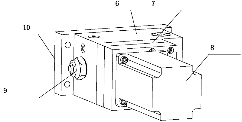
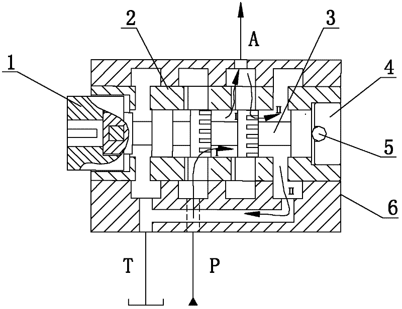
[0014] refer to Figure 1 ~ Figure 3 , a three-way high-frequency excitation valve, including a valve body 6, a valve core 3 and a valve sleeve 2, the valve body 6 is provided with an oil inlet P connected with a high-pressure oil tank, and an oil outlet connected with a hydraulic cylinder Port A, the oil return port T connected to the oil return tank; the valve core 3 and the valve sleeve 2 are located in the valve body 6, the valve sleeve 2 is nested in the valve body hole, the valve core 3 is in the valve sleeve 2, and the valve core There are 4 shoulders on 3, of which the outer two shoulders are supporting shoulders, the middle two shoulders are working shoulders, and the two working shoulders are evenly processed with Z grooves in the circumferential direction, and the two shoulders The grooves on the sleeve are misaligned with each other, and the position of th...


PUM


Abstract

The invention discloses a tee high-frequency electro-hydraulic exciting vibration valve which comprises a valve body, a valve core and a valve sleeve, wherein the valve body is provided with an oil inlet, an oil outlet and an oil return opening, wherein the oil inlet is communicated with a high-pressure oil tank; the oil outlet is communicated with a hydraulic cylinder; the oil return opening is communicated with an oil return oil tank; the valve core and the valve sleeve are positioned in the valve body; the valve sleeve is embedded in a hole of the valve body; the valve core is positioned in the valve sleeve, and is provided with four shoulders, wherein two shoulders at the outer side are support shoulders, and two shoulders in the middle are operating shoulders; grooves are respectively processed axially on the two operating shoulders uniformly, and the grooves of the two operating shoulders are misplaced mutually; valve sleeve windows which are matched with the grooves of the shoulders are uniformly formed circumferentially on the part of the valve sleeve corresponding to the operating shoulders; the distance between the valve sleeve windows is equal to the distance between two operating shoulders; at least three oil wedges are axially formed on the valve sleeve corresponding to the support shoulders at intervals of equal circular arcs; the oil outlet is communicated with a throttle valve; and the throttle valve is installed on the valve body. According to the invention, the shaft diameter deviation is avoided effectively, and the operating stability is good.

Description

technical field [0001] The invention relates to a high-frequency electro-hydraulic excitation valve. Background technique [0002] The existing high-frequency electro-hydraulic vibration valve includes a valve body, and the valve body is provided with an oil inlet connected to the high-pressure oil tank, an oil outlet connected to the hydraulic cylinder, and a return port connected to the oil return tank. oil port; the valve body contains a valve core and a valve sleeve, the valve sleeve is nested in the hole of the valve body, the valve core is inserted into the valve sleeve, and the valve core is connected with the transmission mechanism through a sleeve coupling; There are shoulders, and a certain number of grooves are evenly opened in the circumferential direction of the shoulders, and the grooves on two adjacent shoulders are misaligned; the positions on the valve sleeve corresponding to the middle two shoulders are uniformly opened in the circumferential direction and ...

Claims


Application Information

Patent Timeline
IPC IPC(8): F16K11/08F16K27/06
Inventor 邢彤付亮阮健
Owner ZHEJIANG UNIV OF TECH
Learn More