Energy recycling device for excavator hydraulic system

A technology of energy recovery device and hydraulic excavator, which is applied in the direction of earth mover/shovel, construction, etc., can solve the problems of shortening the service life of components, large damage of hydraulic system, increasing fuel consumption, etc., to reduce the scope and reduce Energy loss, effect of improving fuel economy

Inactive Publication Date: 2015-05-20
SANY HEAVY MACHINERY
View PDF2 Cites 0 Cited by
  • Summary
  • Abstract
  • Description
  • Claims
  • Application Information

AI Technical Summary

Problems solved by technology

One is to increase the fuel consumption; the other is that the impact in a short period of time will cause great damage to the hydraulic system and shorten the service life of the components.

Method used


Image

  • Energy recycling device for excavator hydraulic system

Examples


Embodiment Construction

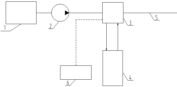
[0013] The present invention will be further described below in combination with principle diagrams and specific operation examples.

[0014] Such as figure 1 As shown, the energy recovery device used in the rear side of the hydraulic excavator main pump includes an engine 1, a main pump 2, a controllable valve group 3, an accumulator 4, a main oil circuit 5, and a controller 6. The energy recovery device Located behind the main pump 2, the main pump 2 is connected to the engine 1, the controllable valve group 3 is located on the main oil circuit 5, and one end is connected to the main pump 2. The oil inlet port and the oil return port of the accumulator 4 are respectively connected with corresponding ports on the controllable valve group 3 . The energy recovery device of the present invention also includes a signal acquisition device (not shown in the figure), and the signal acquisition device can be a common sensor on the market that can measure liquid pressure, such as a h...


PUM


Abstract

The invention discloses an energy recycling device for the rear side of a main pump of a hydraulic excavator. The energy recycling device comprises an engine, the main pump, a controllable valve bank, an energy accumulator, a main oil circuit, a controller and a signal acquisition device. The energy recycling device is located on the rear side of the main pump, the main pump is connected with the engine, the controllable valve bank is located on the main oil circuit, one end of the controllable valve bank is connected with the main pump, an oil inlet and an oil return opening of the energy accumulator are respectively connected with corresponding connectors on the controllable valve bank, and the controller is connected with the controllable valve bank, measures pressure of the oil circuit via the signal acquisition device, and accordingly controls the controllable valve bank. Energy transfer and storage can be realized when power of the engine is redundant, and in an excavation process of the excavator, supplementing of oil is realized. Energy when the power of the engine is redundant is utilized, accordingly, a power fluctuation range of the engine is reduced, hydraulic impact in the excavation process is reduced, and fuel utilization rate is improved.

Description

technical field [0001] The invention relates to the technical field of energy recovery of a hydraulic excavator, in particular to an energy recovery device used at the rear side of a main pump of a hydraulic excavator. Background technique [0002] At present, when the hydraulic excavator has no major movements, if the engine power is relatively constant, the engine power is often greater than the power required by the system, and a part of the hydraulic oil output by the main pump returns to the oil tank through overflow and does not participate in work, which affects the engine power. cause waste. When doing big actions such as digging, the power fluctuates in a large range in a short period of time, which breaks the state of the engine and the main pump working at approximately constant power. This one is to increase the fuel consumption; the other is that the impact in a short period of time will cause great damage to the hydraulic system and shorten the service life of...

Claims


Application Information

Patent Timeline
Patent Type & Authority Patents(China)
IPC IPC(8): E02F9/22
Inventor 胡奇邹云川陈文刚
Owner SANY HEAVY MACHINERY
Why Eureka
Try Eureka