
Horizontal moving mechanism for needle bed of computer flat knitting machine

A technology of traversing mechanism and flat knitting machine, which is applied in the directions of knitting, weft knitting, textiles and papermaking, can solve the problem of lack of needle beds, and achieve the effects of improving the knitting speed, the overall structure and the production efficiency.

Inactive Publication Date: 2012-07-04
江苏雪亮电器机械有限公司
View PDF8 Cites 4 Cited by
  • Summary
  • Abstract
  • Description
  • Claims
  • Application Information

AI Technical Summary

Problems solved by technology

Another example is that the utility model authorized announcement number CN201198518Y provides "transverse transmission device for computerized flat knitting machine". no reference

Method used


Image

  • Horizontal moving mechanism for needle bed of computer flat knitting machine
  • Horizontal moving mechanism for needle bed of computer flat knitting machine
  • Horizontal moving mechanism for needle bed of computer flat knitting machine

Examples


Embodiment Construction

[0020] In order to enable the examiners of the patent office, especially the public, to understand the technical essence and beneficial effects of the present invention more clearly, the applicant will describe in detail the following in the form of examples, but none of the descriptions to the examples is an explanation of the solutions of the present invention. Any equivalent transformation made according to the concept of the present invention which is merely formal but not substantive shall be regarded as the scope of the technical solution of the present invention.

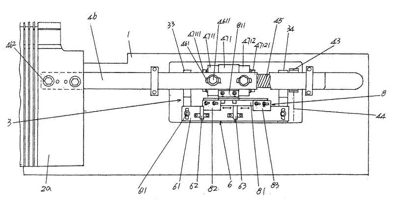
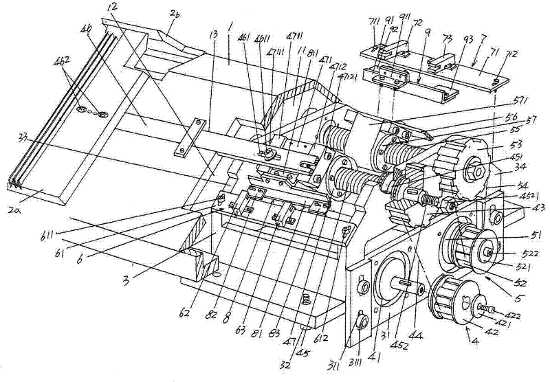
[0021] Please see figure 1 and figure 2 , a frame 1 is given, the cross-sectional shape of the frame 1 is generally a figure-eight shape, and the frame 1 has (formed with) a frame cavity 11 by the shape of the figure-eight cross-section, in which A relief cavity 12 corresponding to each other is provided on the frame walls of the front side and the rear side of the frame 1 . A front needle bed 2a is ...


PUM


Abstract

The invention relates to a horizontal moving mechanism for a needle bed of a computer flat knitting machine, which belongs to the technical field of knitting mechanisms. The computer flat knitting machine comprises a rack, a front needle bed and a rear needle bed, wherein a rack cavity is formed on the bottom part of the rack; the front needle bed is arranged on the front side of the rack; and the rear needle bed is arranged on the rear side of the rack and is corresponding to the front needle bed. The horizontal moving mechanism for the needle bed comprises a screw bracket, a front needle bed driving device, a rear needle bed driving device, a front needle bed position signal collecting device, a rear needle bed position signal collecting device, a first signal sensing device and a second signal sensing device, wherein the screw bracket is arranged in the rack cavity and is fixed with the rack; a motor base is arranged on one end of the screw bracket; the front needle bed driving device is arranged on the screw bracket; the rear needle bed driving device is arranged on the screw bracket; the front needle bed position signal collecting device is fixedly arranged on the upper part on one side of the screw bracket; the rear needle bed position signal collecting device is fixedly arranged on the upper part on the other side of the screw bracket; the first signal sensing device is fixed with the front needle bed driving device; and the second signal sensing device is fixed with the rear needle bed driving device. The horizontal moving mechanism for the needle bed of the computer flat knitting machine has the advantages of wide application range, high production efficiency and simple overall structure, and the computer flat knitting machine in the prior art can be configured as well.

Description

technical field [0001] The invention belongs to the technical field of knitting mechanisms, and in particular relates to a needle bed traverse mechanism of a computerized flat knitting machine. Background technique [0002] As is well known in the industry, the computerized flat knitting machine has functions such as automatic row counting, automatic needle addition and subtraction, automatic yarn change, automatic loop transfer, and automatic needle transfer during pick-up. In order to ensure the smooth knitting of the knitting mechanism, it is equipped with There is a needle bed traverse mechanism, and the needle bed traverse mechanism makes the needle bed traverse. For example, when weaving pick-up fabrics, it is necessary to move the loops from the knitting needles on one side (one side of the needle bed, such as the knitting needles on the front needle bed) to the knitting needles on the other side of the needle bed, and sometimes it is necessary to stagger one or A pl...

Claims


Application Information

Patent Timeline
Patent Type & Authority Applications(China)
IPC IPC(8): D04B15/12
Inventor 邵锡良
Owner 江苏雪亮电器机械有限公司
Learn More