
Fixation aid for brain electrode lead

An auxiliary device and electrode lead technology, applied in the directions of internal electrodes, head electrodes, electrodes, etc., can solve the problems of narrow operation space and inconvenient operation for doctors, and achieve the effect of easy operation and avoiding target deviation.

Active Publication Date: 2014-09-17
SCENERAY
View PDF4 Cites 0 Cited by
  • Summary
  • Abstract
  • Description
  • Claims
  • Application Information

AI Technical Summary

Problems solved by technology

There is no such special auxiliary device for fixing brain electrode wires in the prior art, all of which are done manually by the doctor himself, and the operating space for the doctor during the operation is relatively narrow and the operation is extremely inconvenient

Method used


Image

  • Fixation aid for brain electrode lead
  • Fixation aid for brain electrode lead
  • Fixation aid for brain electrode lead

Examples


Embodiment Construction

[0031] Below in conjunction with accompanying drawing, the present invention is described in further detail:

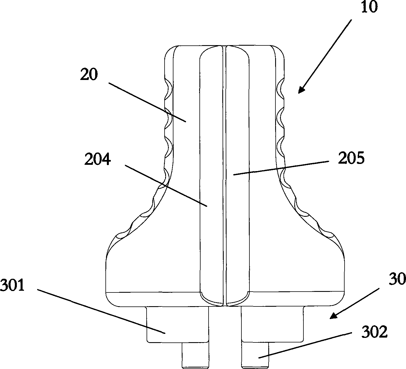
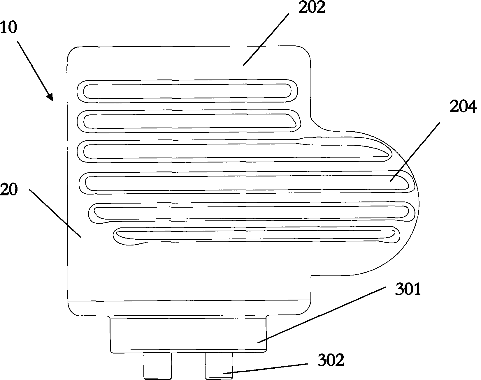
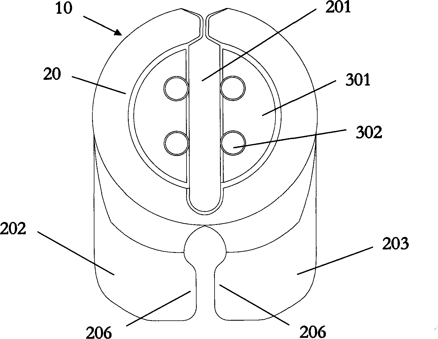
[0032] refer to Figure 1 to Figure 4 , a brain electrode wire fixation auxiliary device 10, comprising an auxiliary device body 20, the lower end of the auxiliary device body 20 extends downward to form a cranial hole plug pressing part 30 extending out of the auxiliary device body 20, the cranial The hole plug depressing part 30 cooperates with the upper surface of the cranial hole plug 40 for plugging the cranial hole plug 40 into the hole of the skull ring 50 .

[0033] The auxiliary device body 20 is provided with a groove 201 penetrating through the pressing portion 30 of the cranial hole plug, and one end of the groove 201 extends to the edge of the auxiliary device body 20 . In this embodiment, the groove 201 is a linear groove, and in some other embodiments, the groove 201 may also be a curved groove or a cross-line groove.

[0034] The outer surface of the...


PUM


Abstract

Disclosed is a brain electrode lead auxiliary device (10). The device comprises an auxiliary device body (20); the lower end thereof extends downwards and forms a cranial burr hole plug pressing portion (30) protruding out of the auxiliary device body, with the cranial burr hole plug pressing portion fitting the upper surface of the cranial burr hole plug to insert the cranial burr hole plug into the hole of a cranial burr hole grommet. The solution enables doctors to press down and fasten the cranial burr hole plug securely in the cranial burr hole grommet within a relatively small space during surgery. After the electrode lead reaches the designated target via a lead guiding needle, a doctor pulls out the lead guiding needle; at this time, the cranial burr hole plug immediately holds and tightly clips the electrode lead, such that the electrode does not move in the horizontal direction or the vertical direction, anchoring the electrode lead securely and accurately at the designated target position, and avoiding the phenomenon of target deviation from occurring during the operation to close the cranial burr hole grommet by the doctor, so that cause the entire surgical operation is convenient.

Description

technical field [0001] The invention relates to the field of implantable medical systems, in particular to a fixation auxiliary device for fixing brain electrode wires or other catheters on the skull during the implantation operation of the implantable medical system. Background technique [0002] Implantable medical systems usually include implantable nerve electrical stimulation systems, implantable cardiac electrical stimulation systems (commonly known as cardiac pacemakers), and implantable drug infusion systems. Among them, implantable electrical nerve stimulation systems include deep brain electrical stimulation DBS, implantable cerebral cortex electrical stimulation CNS, implantable spinal cord electrical stimulation SCS, implantable sacral nerve electrical stimulation SNS, implantable vagus nerve electrical stimulation VNS, etc. [0003] Taking the implanted electrical nerve stimulation system as an example, it mainly includes a pulse generator implanted in the body,...

Claims


Application Information

Patent Timeline
Patent Type & Authority Patents(China)
IPC IPC(8): A61N1/05
CPCA61N1/0539
Inventor 不公告发明人
Owner SCENERAY
Learn More