
Micro-robot driven by ciliary vibration

A micro-robot, vibration-driven technology, applied in the fields of vaccination, ovulation diagnosis, medical science, surgery, etc., can solve problems such as damage, application pipeline scratches, and robot application limitations

Inactive Publication Date: 2012-07-04
CHONGQING UNIV OF TECH
View PDF6 Cites 18 Cited by
  • Summary
  • Abstract
  • Description
  • Claims
  • Application Information

AI Technical Summary

Problems solved by technology

[0004] The above-mentioned micro-robot driven by the vibration of multiple burrs, because of the use of hard unidirectional metal-like burrs as the driving method, is likely to cause scratches or even damage to the inner wall of the application pipeline (cavity), and because the burrs with a single side inclined , so it can only move in one direction, and cannot actively change the direction and speed of travel
At the same time, the miniature burr robot adopts a circular shape structure, which requires the burr of the robot to be in good contact with the inner wall of the applied pipe, which makes the burr robot only suitable for occasions with a certain pipe diameter. Changes will affect the application performance of the robot
At the same time, the micro-burr robot adopts a wired energy supply or control method, which will prevent the micro-robot from returning on the original path, which further limits the application of the robot.
Therefore, there are defects in the prior art, which need to be improved and developed

Method used


Image

  • Micro-robot driven by ciliary vibration
  • Micro-robot driven by ciliary vibration
  • Micro-robot driven by ciliary vibration

Examples


Embodiment Construction

[0026] The specific embodiments of the present invention will be further described below in conjunction with the accompanying drawings.

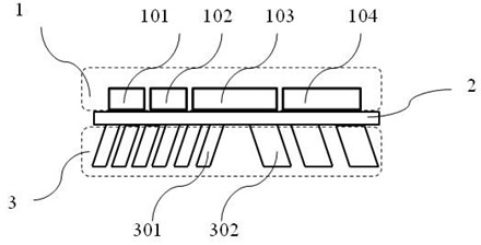
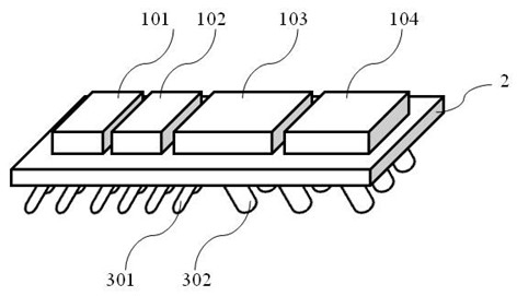
[0027] see figure 1 and figure 2 , the micro-robot is composed of a three-layer structure. The upper structure 1 includes a power supply module 101, a control circuit module 102, a vibration motor module 103 and an operation module 104; the middle layer structure 2 is a substrate for supporting and connecting; The functional cilia driving legs are divided into the first group of cilia driving legs 301 and the second group of cilia driving legs 302 . The two groups of ciliary driving legs in the lower structure 3 have different numbers, different diameters, and symmetrical inclination angles. They are processed under the middle layer structure 2 through abrasive infusion technology, and form a whole with the middle layer structure 2. The middle layer structure 2 and the lower structure 3 are all made of PDMS material, which has good flexi...


PUM


Abstract

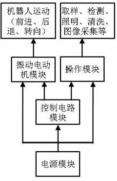
The invention discloses a micro-robot driven by ciliary vibration. The micro-robot consists of a three-layer structure, wherein an upper layer comprises a power module, a vibrating motor module, a control circuit module and an operation module; an intermediate layer is a base plate which has supporting and connecting effects; and a lower layer at least comprises two groups of cilia driving legs with different quantities, different diameters, symmetrical inclination angles, equal total horizontal sectional areas and equal vertical heights. The cilia driving legs vibrate and swing under the vibration action of different rotating speed of a vibrating motor; and the diameters of the cilia driving legs are different, so the natural vibration frequencies of the cilia driving legs are different, and the vibration amplitudes are also different. When the vibration frequency of the vibrating motor is close to the natural vibration frequencies of the cilia driving legs, the vibration amplitudes of the cilia driving legs are increased; and when the vibration frequency of the vibrating motor is far away from the natural vibration frequencies of the cilia driving legs, the vibration amplitudes of the cilia driving legs are decreased. The rotating speed of the vibrating motor can be controlled by using the control circuit module further to fulfill the aims of controlling the forwardness, backwardness, steering and adjustment of travel speed of the micro-robot.

Description

technical field [0001] The invention relates to micro-robot technology, in particular to a micro-robot driven by cilia vibration. Background technique [0002] In the past ten years, with the rapid development of robotics and micro-processing technology, micro-robot technology has been applied to many fields such as machinery, chemistry and medical clinical diagnosis. In-pipe mobile micro-robots are an important application direction in the field of micro-robots. They can be widely used in the detection and information collection of small-diameter pipes (or cavities) in industries such as electric power, chemical industry, heating, and biomedicine. s concern. At present, a variety of micro-robots have been reported in various academic journals, most of which are driven by wheels, crawlers, or joint telescopic peristalsis. The mainstream driving method currently studied is wheel drive, but because the size of the driving wheel and the transmission mechanism cannot be truly ...

Claims


Application Information

Patent Timeline
Patent Type & Authority Applications(China)
IPC IPC(8): A61B1/00A61B5/07A61B10/04
Inventor 崔建国
Owner CHONGQING UNIV OF TECH
Learn More