Matrix array switching value driver

A switching value and driver technology, applied in the direction of logic circuits using basic logic circuit components, logic circuits using specific components, etc., can solve the problems of insufficient utilization of IO resources and complicated wiring, and reduce the number of output points configuration and wiring. , the effect of improving the efficiency of use

Inactive Publication Date: 2014-06-04
BAOJI PETROLEUM MASCH CO LTD +2
View PDF11 Cites 0 Cited by
  • Summary
  • Abstract
  • Description
  • Claims
  • Application Information

AI Technical Summary

Problems solved by technology

[0003] The purpose of the present invention is to provide a matrix switch driver, which solves the problems of complex wiring and insufficient utilization of IO resources when a large number of switch outputs required by the prior art control system

Method used


Image

  • Matrix array switching value driver
  • Matrix array switching value driver
  • Matrix array switching value driver

Examples


Embodiment Construction

[0024] The present invention will be described in detail below in conjunction with the accompanying drawings and specific embodiments.

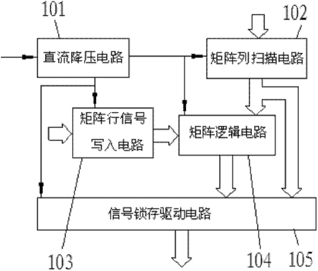
[0025] refer to figure 1 , the modular connection structure of the matrix type switching value driver of the present invention is, comprises DC step-down circuit 101, matrix row scanning circuit 102, matrix line signal writing circuit 103, matrix logic circuit 104 and signal latch drive circuit 105 five-part connection composition. Wherein the DC step-down circuit 101 is respectively connected with the corresponding power end of the matrix row scanning circuit 102, the matrix row signal writing circuit 103, the matrix logic circuit 104, and the signal latch driving circuit 105, and the matrix row scanning circuit 102 and the matrix row signal writing The output terminal of the input circuit 103 is connected to the corresponding input terminal of the matrix logic circuit 104 at the same time, and the output terminals of the matrix column scan...


PUM


Abstract

The invention discloses a matrix array switching value driver, which comprises a direct-current step-down circuit. The direct-current step-down circuit is respectively connected with corresponding power ends of a matrix array scanning circuit, a matrix array signal write circuit, a matrix array logic circuit, a signal latching drive circuit, and output ends of the matrix array scanning circuit and the matrix array signal write circuit are simultaneously connected with corresponding input ends of the signal latching drive circuit. The switching value driver is used for matrix array scanning based on matrixes and coding in a binary system, 64 switching value equipment can be controlled by 12 output points of a controller, 128 switching value equipment can be controlled by 13 output points, and multiplied extension of capacity can be realized by controlling enable terminals EN allowed to be selected by different drivers, so that output channels are greatly saved, wiring is simple when in remote acquisition, and cost is low.

Description

technical field [0001] The invention belongs to the technical field of automation control, and relates to a matrix switching value driver. Background technique [0002] With the automation of equipment getting higher and higher, the control system needs to control more and more field variables, especially the control of various switches. One point needs to occupy one output point of the controller, and the hardware resources are particularly limited. , in the development of embedded systems, in many cases, IO resources cannot meet the use requirements. For example, if PLC control is used, a large number of output modules need to be added, and racks are added for expansion, which increases hardware costs and requires a large installation space. At the same time, wiring It is also very complicated; the distributed site acquisition interface of the commonly used bus is not open, requiring the controller to have the corresponding bus resources, the cost is high, and the use is n...

Claims


Application Information

Patent Timeline
Patent Type & Authority Patents(China)
IPC IPC(8): H03K19/177
Inventor 梁春平丛万生张鹏飞刘启蒙宋涛
Owner BAOJI PETROLEUM MASCH CO LTD
Why Eureka
Try Eureka