Rotor punching sheet of high-speed permanent magnet motor

A technology for punching permanent magnet motors and rotors, which is applied to the rotating parts of the magnetic circuit, the shape/style/structure of the magnetic circuit, etc., and can solve the problems of complete machine scrapping and motor jamming

Inactive Publication Date: 2012-06-27
DALIAN YULIN ELECTRIC MOTOR
View PDF0 Cites 2 Cited by
  • Summary
  • Abstract
  • Description
  • Claims
  • Application Information

AI Technical Summary

Problems solved by technology

[0002] In the prior art, the punching plate of the motor rotor is not provided with an inner groove of the punching plate, and the permanent magnet block of the rotor is directly installed outside the rotor or blocked on the periphery of the rotor through a baffle plate, so that when the air gap of the motor is small, it is small and loose The permanent magnet block is likely to exceed the air gap, causing the motor to be stuck and the whole machine to be scrapped

Method used


Image

  • Rotor punching sheet of high-speed permanent magnet motor
  • Rotor punching sheet of high-speed permanent magnet motor

Examples


Embodiment Construction

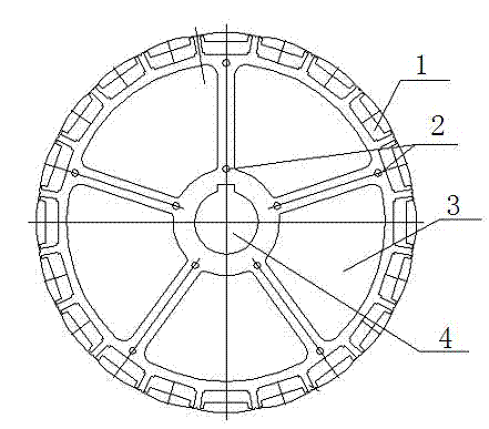
[0009] Such as figure 1 As shown, the high-speed permanent magnet motor rotor punching sheet includes punching sheet inner slot 1, punching sheet combined hole 2, weight reducing hole 3 and rotor shaft hole 4. The punching sheet inner slot 1 is distributed on the outer circumferential surface of the punching sheet to reduce The heavy holes 3 are distributed around the rotor shaft holes 4, the punching piece combination holes 2 are arranged between the weight-reducing holes 3, the rotor shaft hole 4 is arranged at the center of the punching piece, and the weight-reducing holes 3 are sector-shaped. The high-speed permanent magnet of the present invention The motor rotor punching piece, the permanent magnet block is inserted in the inner slot of the punching piece, which can prevent the permanent magnet block from falling off at high speed. The overall punching piece structure makes the magnetic flux form a closed circuit to prevent the permanent magnet block from losing its magnet...


PUM


Abstract

The invention discloses a rotor punching sheet of a high-speed permanent magnet motor. The rotor punching sheet comprises punching sheet inner slots (1), punching sheet combined holes (2), lightening holes (3) and a rotor shaft hole (4), wherein the punching sheet inner slots (1) are distributed on an outer circumferential surface of the punching sheet, the lightening holes (3) are arranged around the rotor shaft hole (4) in a surrounding manner, the punching sheet combined holes (2) are arranged among the lightening holes (3), and the rotor shaft hole (4) is arranged at the center of the punching sheet. According to the rotor punching sheet of the high-speed permanent magnet motor disclosed by the invention, a permanent magnet block is embedded in the punching sheet inner slot so that the permanent magnet block can be prevented from falling off during a high-speed operation; due to an integrated punching sheet structure, a magnetic flux forms closed circulation so as to prevent the permanent magnet block from loss of excitation, and the service life of the permanent magnet motor is prolonged; and reverse installation of the punching sheet is avoided by utilizing asymmetrical webs in the punching sheet.

Description

Technical field [0001] The invention relates to a high-speed permanent magnet motor rotor punching sheet. Background technique [0002] In the prior art, the punching piece of the rotor of the motor is not provided with the inner groove of the punching piece, and the permanent magnet block of the rotor is directly installed outside the rotor or blocked by the baffle at the periphery of the rotor. In this way, it is small and loose when the air gap of the motor is small. The permanent magnet block is very likely to exceed the air gap, causing the motor to jam and the whole machine to be scrapped. Summary of the invention [0003] The purpose of the present invention is to provide a high-speed permanent magnet motor rotor punching piece which can prevent the permanent magnet block from falling off at high speed. [0004] The technical scheme adopted by the present invention to achieve the above objective is: a high-speed permanent magnet motor rotor punching sheet, including punching...

Claims


Application Information

Patent Timeline
IPC IPC(8): H02K1/27
Inventor 孙淑娥
Owner DALIAN YULIN ELECTRIC MOTOR
Why Eureka
Try Eureka