Eureka AIR delivers breakthrough ideas for toughest innovation challenges, trusted by R&D personnel around the world.

Coloring reuse method for micro-polygon ray tracing

A ray tracing and polygon technology, applied in 3D image processing, instrumentation, calculation, etc., can solve the problems of unavailable highlight reflection and ineffective mapping, so as to reduce the amount of shading calculation, improve performance, and ensure accuracy. Effect

Active Publication Date: 2012-06-27
ZHEJIANG UNIV
View PDF3 Cites 12 Cited by
  • Summary
  • Abstract
  • Description
  • Claims
  • Application Information

AI Technical Summary

Problems solved by technology

However, the same approach cannot be used to handle effects such as specular reflections in ray tracing, because these effects involve a non-continuous mapping of objects into image space, which cannot be effectively handled by the image space methods described above

Method used


Image

  • Coloring reuse method for micro-polygon ray tracing

Examples


Embodiment 1

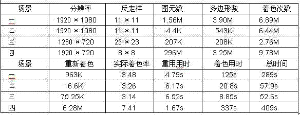
[0030] Example one The inventor used the method of the present invention to draw four typical scenes, including a common battle scene in a movie (scene 1), a scene with a magnifying glass with reflection / refraction and a metal object with displacement maps (scene 2), and There are scenes with motion-blurred cars passing through tunnels (Scene 3) and a highly complex scene with waterside castles and woods (Scene 4). Table 1 shows the performance statistics of the method of the present invention in all scenes. Among them, the reuse time is all the extra time reused for coloring, including the time for constructing kd trees, searching for nearest neighbors, and collecting recoloring samples. The actual shading rate is the average number of shading calculations on each pixel actually measured. Due to the layering of the scene and the need to recalculate the shading, this value is generally slightly larger than the shading rate specified by the user. As shown in the table, the meth...

Embodiment 2

[0033] Example two The inventor compared the results of the non-reuse coloring results, the results of this method, and the results of the decoupled sampling method as a reference in the second scenario above. For decoupled sampling methods, please refer to RAGAN-KELLEY, J., LEHTINEN, J., CHEN, J., DOGGETT, M., AND DURAND, F. 2011. Decoupled sampling for graphics pipelines. ACM Trans. Graph. 30, 3 ( May), 17:1–17:17. The result is that the results of this method are visually consistent with the reference results. In the decoupling sampling method, the coloring value will only be reused between samples belonging to the same primitive and these samples have the same hash value under the standard decoupling mapping, where the decoupling mapping calculates the sample by projecting the sample onto the image plane The integer hash value of, defocus is not considered during the projection process. Since this mapping does not consider the magnification and deformation caused by ray...


PUM


Abstract

The invention discloses a coloring reuse method for accelerating micro-polygon ray tracing, wherein the coloring computation is greatly reduced on the premise that the rendering quality is ensured, and the rendering efficiency is improved. According to the coloring reuse method, firstly, a group of coloring rays with the number specified by a user is projected from an image space, and coloring values computed according to the rays are assigned to an anti-aliasing sample through nearest neighbor searching. In order to reduce the interferential reuse of different types of optical paths, different layers are marked out according to the first reflection type of the optical paths, and each layer undergoes coloring sampling. Compared with the existing coloring reuse technology, the coloring reuse method has no need to explicitly indicate the mapping mode of objects to image space, and can also process the ray tracing effects such as refection and refraction more concisely. The coloring reuse method can be realized in a highly-parallelized mode based on graphic processing hardware, and the efficiency of the micro-polygon ray tracing is increased by an order of magnitude.

Description

technical field [0001] The invention relates to the technical field of graphics drawing, in particular to a micro-polygon-oriented ray tracing method. Background technique [0002] Shading is often the performance bottleneck for film-quality rendering. This rendering is usually based on the Reyes architecture, which uses micropolygons to represent high-order surfaces or very fine-grained objects. For the definition of Reyes architecture and micropolygons, please refer to: COOK, R. L., CARPENTER, L., AND CATMULL, E. 1987; The Reyes image rendering architecture. SIGGRAPH Computer Graphics 21, 4 (August), 95–102. In order to reduce the cost of shading, advanced micro-polygon renderers (such as RenderMan from Pixar) perform shading calculations on the vertices of micro-polygons, and then reuse the shading values ​​to calculate the color of each visibility sample (or anti-aliasing sample), and then synthesize the final image. Such a shading reuse strategy can make the shading ...

Claims


Application Information

Patent Timeline
IPC IPC(8): G06T15/06
Inventor 侯启明周昆
Owner ZHEJIANG UNIV
Why Eureka
Eureka Blog
Learn More