
Shaft-type daylighting and ventilation device and method thereof

A ventilation device and shaft-type technology, which is applied in the direction of vertical pipes, buildings, building components, etc., can solve the problem of no lighting system and ventilation system in the shaft

Inactive Publication Date: 2012-06-27
TIANJIN ARCHITECTURE DESIGN INST +2
View PDF4 Cites 8 Cited by
  • Summary
  • Abstract
  • Description
  • Claims
  • Application Information

AI Technical Summary

Problems solved by technology

[0002] The existing shaft has no lighting system and ventilation system, it is only for smoke exhaust

Method used


Image

  • Shaft-type daylighting and ventilation device and method thereof
  • Shaft-type daylighting and ventilation device and method thereof

Examples


Embodiment Construction

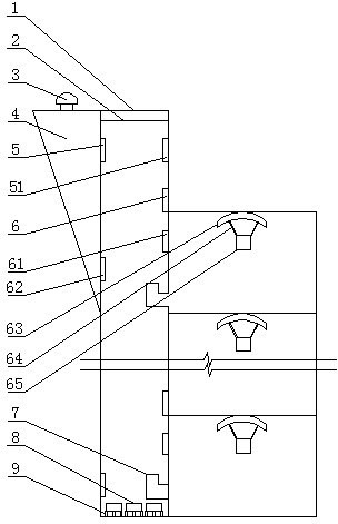
[0011] Shaft lighting system: the top of the shaft is equipped with a light-transmitting mirror such as figure 1 As shown in (1), the lower part is provided with a concentrating glass group such as figure 1 As shown in (2), (1) and (2) are hollow in the middle, which insulates part of the heat. When installing (1), the angle needs to be adjusted to the best lighting angle with reference to the local sunlight incident angle, and (2) and (1) can be installed in parallel. In the shaft by the main reflector such as figure 1 (5), the reflected sunlight from the upper part enters the sub-reflector (51), receives the light from (5) and reflects downwards, enters the reflector (62), and then reflects into the condenser (61), the light Access to the solar lighting system inside the room. The reflector (8) at the bottom of the shaft injects the light transmitted from the upper part into the room through the concentrator in the room on the first floor without waste, and (8) the...


PUM


Abstract

The invention relates to a shaft-type daylighting and ventilation device and a method thereof. A daylighting and ventilation pipe and a pipeline form a shaft, wherein a multistage reflection device is arranged in the shaft and fixed in a special position of the shaft, and external light enters into the shaft through a top photic plate to realize the internal daylighting function of the shaft. An exhaust outlet and an exhaust fan are arranged at the upper part of a ventilation shaft; each floor is connected to a daylighting shaft; and an exhaust outlet is arranged at the lower part of the floor, so that contaminated air in rooms can be exhausted from the exhaust outlet at the lower part. The invention can be widely applied to devices built and equipped in various shafts and the application method of the devices, can realize an industrialized, normalized and universalized energy conservation and emission reduction method for a building, and belongs to the daylighting and ventilation fields of buildings.

Description

technical field [0001] The invention relates to a shaft-type lighting and ventilation device and method. The upper part of the shaft is composed of a lighting shaft and a ventilation shaft. The lighting shaft and the ventilation shaft are connected internally without being separated. Set the light-transmitting board and the reflector in the lighting shaft, and fix them in the special position of the shaft, and the external light enters the inside of the shaft through the top light-transmitting plate, so as to achieve the purpose of lighting inside the shaft. An exhaust outlet and an exhaust fan are installed on the upper part of the ventilation shaft, each floor is connected to the lighting shaft, and an exhaust outlet is installed on the lower part, and the dirty air in the house is discharged through the lower exhaust outlet. The device and implementation method that can be widely used in various vertical shafts are constructed and equipped, and the energy-saving and emissi...

Claims


Application Information

Patent Timeline
IPC IPC(8): E04F17/04E04F17/06
Inventor 张鸿瑞刘勇胜杨玉琴藏成平臧筑华仝贵来王绍妍黄兆纬周国民杨志艳李济云张洪生杨永安魏德立
Owner TIANJIN ARCHITECTURE DESIGN INST
Learn More