
Device for reducing water ratio of sludge

A technology of moisture content and sludge, applied in the field of resource treatment, can solve the problems of reducing the moisture content of sludge, the ability of moisture and heavy metals to decrease, and the degree of sludge moisture reduction to be different, and to achieve the effect of saving cement consumption.

Inactive Publication Date: 2012-06-20
HOHAI UNIV
View PDF4 Cites 2 Cited by
  • Summary
  • Abstract
  • Description
  • Claims
  • Application Information

AI Technical Summary

Problems solved by technology

Electrodynamic technology can enrich water and heavy metals to the cathode (negative electrode), and the area near the anode (positive electrode) can form a dry soil area with a very low moisture content. However, with the formation of the dry soil area (resistance increases, the current decreases ), its ability to transport water and heavy metals will decrease rapidly, and because of the enrichment of water, the moisture content of the soil at the cathode will increase
It has also been suggested that vacuuming and electric power technology can be combined to use lower soil moisture content, but their vacuum plate positions and electrode positions are fixed. After vacuuming and powering on for a certain period of time, the problem of low efficiency cannot be solved, and the sludge The degree of moisture reduction in different regions is not the same
In addition, the combined method cannot eliminate or reduce the problem of heavy metal pollution
Cement can be used to solidify the heavy metals in the sludge, so that it will no longer precipitate and form pollution, but the amount of cement in this method should reach 30-40% of the sludge volume, or even more, which is very uneconomical
[0003] In short, there is still no effective and economical method and supporting equipment that can simultaneously reduce the moisture content of sludge and prevent secondary pollution by heavy metals.

Method used


Image

  • Device for reducing water ratio of sludge
  • Device for reducing water ratio of sludge
  • Device for reducing water ratio of sludge

Examples


Embodiment Construction

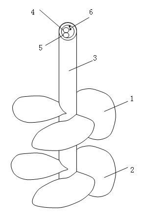
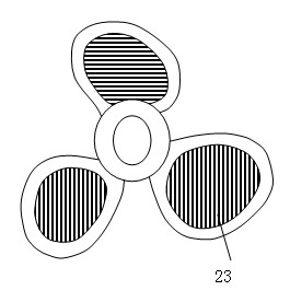
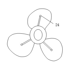
[0022] Below in conjunction with accompanying drawing, the present invention is described in detail, as figure 1 As shown, a device for reducing moisture content is composed of an upper screw blade 1, a lower screw blade 2, a hollow rotating shaft 3, and a drainage pipe 4. The shape of the upper and lower blades is similar to that of a propeller, and the lower screw blade A shallow groove is opened on the upper side of the blade, and a rubber pad 21, a filter cloth 22 and a thick steel bar grate 23 are successively installed on the shallow groove, see Figure 4 . Such as figure 2 , image 3 As shown, a shallow groove is provided on the lower side of the lower blade, so that the cement spray nozzle 24 is arranged in the shallow groove on the lower surface. The lower side of the upper helical blade is provided with shallow grooves, and rubber pads and conductive plates 11 are installed on the shallow grooves, see Figure 5 . Described transmission shaft 3 is a hollow steel...


PUM


Abstract

The invention discloses a device for reducing water ratio of sludge. The device for reducing the water ratio of the sludge comprises a hollow transmission shaft, wherein a water drain pipe is arranged inside the improved transmission shaft; an upper spiral blade and a lower spiral blade are arranged on the transmission shaft; an electrically-conductive plate is arranged below the upper spiral blade; the electrically-conductive plate is insulated from the upper spiral blade; a metal water filtering layer is arranged on the upper surface of the lower spiral blade; the metal water filtering layer is insulated from the lower spiral blade; a power cord is arranged inside the transmission shaft; the positive electrode of a power supply is connected to the electrically-conductive plate; and the negative electrode of the power supply is connected to the metal water filtering layer. Compared with the prior art, under the action of an electromotive force, water migrates towards the lower blade,while a vacuumizing position is rightly above the lower blade, so that the vacuumizing efficiency is improved; and along with the downward movement of the upper blade, the upper blade is always separated from dry sludge to be in contact with the sludge with relatively high water ratio, so that the water and heavy metal migrating capability of the electromotive force is improved.

Description

technical field [0001] The invention relates to the technical fields of environment, civil engineering and water conservancy, in particular to resource treatment of polluted sludge. Background technique [0002] If the sludge with high water content and rich in heavy metals is not treated, it will easily cause secondary pollution if it is piled up randomly, and it will occupy the site. In order to make it resourceful, it is necessary to reduce the water content and reduce the ionization of heavy metal ions. Vacuumizing is one of the methods to reduce the moisture content, but it can only effectively reduce the moisture in the local area near the vacuum plate, and the moisture reduction efficiency is low in the area far away from the vacuum plate. Electrodynamic technology can enrich water and heavy metals to the cathode (negative electrode), and the area near the anode (positive electrode) can form a dry soil area with a very low moisture content. However, with the formatio...

Claims


Application Information

Patent Timeline
IPC IPC(8): C02F11/12
Inventor 殷德顺张伟王保田
Owner HOHAI UNIV
Learn More