
Rectangular cast-in-place pile slotting combined drilling rig

A technology of combined drilling tools and cast-in-situ piles, which is applied in the direction of drilling tools, drill bits, earthwork drilling and mining, etc. It can solve problems such as difficulties, hole diameter enlargement, and uneconomical problems, and achieve obvious effects, good pile shape, and remarkable effects

Inactive Publication Date: 2012-06-13
CHINA STATE CONSTR HARBOR CONSTR
View PDF5 Cites 2 Cited by
  • Summary
  • Abstract
  • Description
  • Claims
  • Application Information

AI Technical Summary

Problems solved by technology

This process mainly has the disadvantages of slow construction speed and difficulty in pressing down the steel cage, especially the current pile foundation construction size section is getting larger and deeper, and the adaptability of this construction process is not strong.
[0005] The construction of hydraulic grab adopts direct grabbing into groove construction, the main problem and disadvantage is that the adaptability to the interface size of rectangular cast-in-situ piles is not strong
It is very uneconomical to have a new set of buckets and guide plates for a rectangular cast-in-place pile with a cross-sectional size
In addition, due to the one-grab construction of the hydraulic grab, if the verticality is not well controlled, it will be difficult to lift the bucket body up and down, which will cause the aperture to continuously enlarge, and in severe cases, machine damage such as buried buckets will occur
[0006] The main problem in the construction of rectangular sections by rotary drilling and row drilling is that the section is not well adaptable. When the aspect ratio of the section of rectangular cast-in-situ piles is less than 2, rotary drilling can only be used for single-hole construction, and other soil extraction techniques are still required for the remaining soil at the pile site. In addition, the verticality of the groove formed by the rotary drill can not meet the design requirements of 1 / 300

Method used


Image

  • Rectangular cast-in-place pile slotting combined drilling rig
  • Rectangular cast-in-place pile slotting combined drilling rig

Examples


Embodiment Construction

[0023] In order to make the technical means, creative features, goals and effects achieved by the present invention easy to understand, the present invention will be further described below in conjunction with specific illustrations.

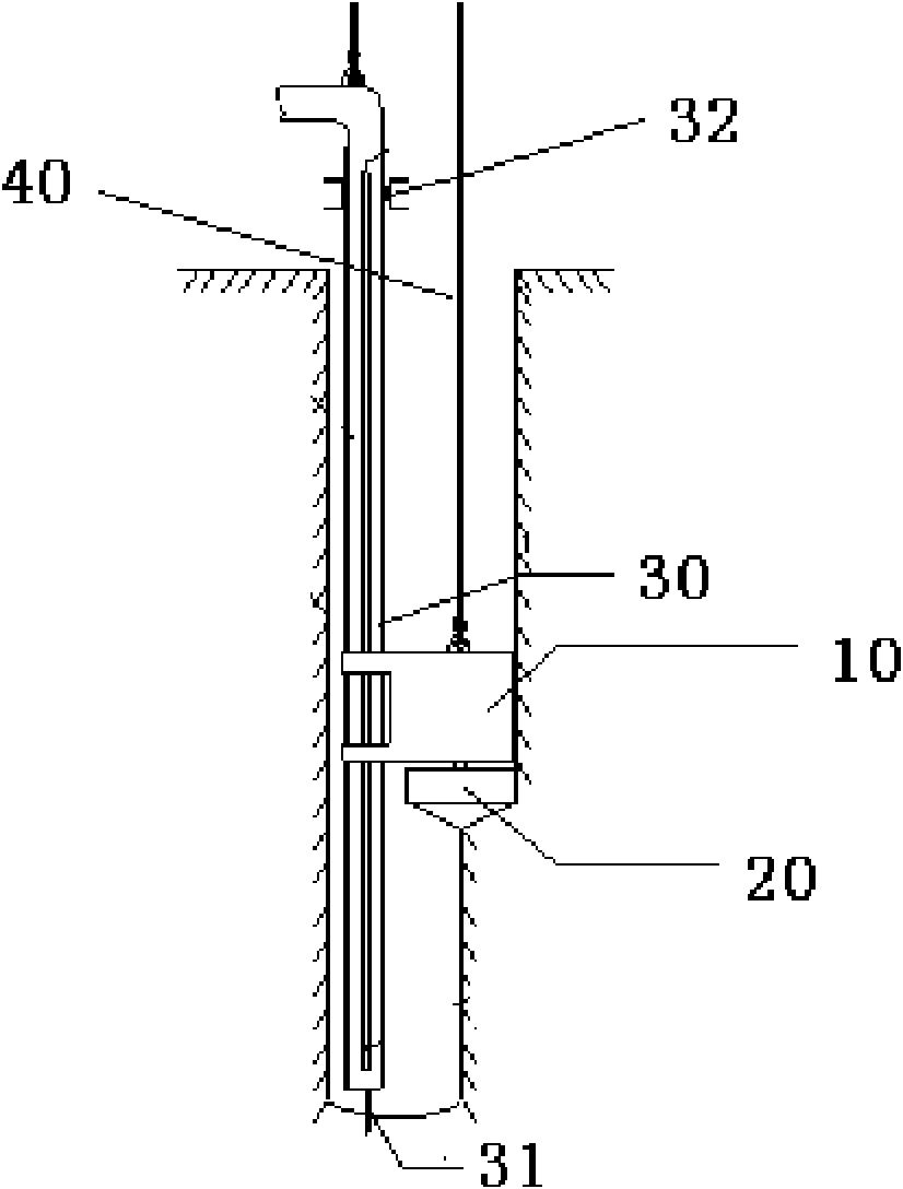
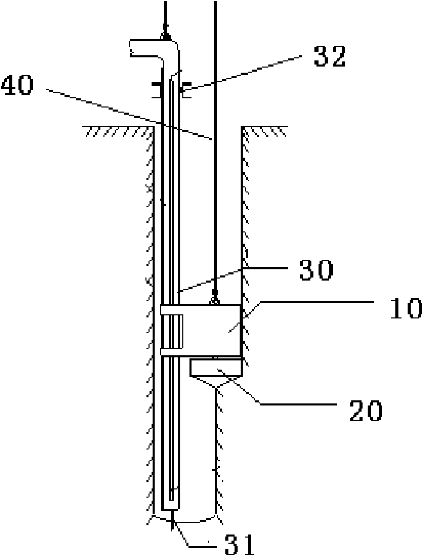
[0024] see figure 1 Shown, a kind of rectangular cast-in-place pile of the present invention is grooved combination drilling tool, and described drilling tool comprises submersible drilling rig 10, is arranged on the cage type combined drill bit 20 of submersible drilling rig 10 lower end and is arranged on the spray pipe 30 of one side of submersible drilling rig, so The spray pipe 30 is connected with the frame (not shown in the figure), and the upper end of the submersible drilling rig 10 is connected with the frame through a wire rope 40 .

[0025] Groove trimmers (not shown in the figure) are provided on the four side edges of the submersible drilling rig 10 of the present invention. The groove trimmers can be cutting blades, and the cuttin...


PUM

PropertyMeasurementUnit
Diameteraaaaaaaaaa

Abstract

The invention discloses a rectangular cats-in-place pile slotting combined drilling rig. The drilling rig comprises an under water rig, a cage type combined drill which is arranged at the lower end of the under water rig, and a spray guide pipe which is arranged on one side of the under water rig; the spray guide pipe is connected with a rack; and the upper end of the under water rig is connected with the rack through a steel rope. According to the drilling rig, the cage type combined drill cuts a soil body from top to bottom, holes are formed primarily by using slot correction devices of the fixed under water rig, and the all-section overlapped slot position correction is performed by using a special rectangular section smasher, so the hole forming of a rectangular cast-in-place pile is finished well. A reinforcement cage can be placed smoothly, a section is excavated after construction, and a pile has a good shape. A spray guide pipe process air lift reverse circulation deslagging method is adopted, and an obvious deslagging effect and a slurry changing effect are achieved; and pile verticality is 1 / 300 required by the design.

Description

technical field [0001] The invention relates to a cast-in-place pile grooving machine tool, in particular to a rectangular cast-in-situ pile grooving combined drilling tool. Background technique [0002] Compared with the circular cast-in-place pile with the same cross-section, the bearing capacity of the friction pile with the same amount of concrete is increased by more than 16% for the rectangular cast-in-place pile. In addition, the rectangular cast-in-situ pile can fully exert the tensile stress of the steel bar in the concrete section and save the amount of steel bar. When the same amount of steel is used, the horizontal bending resistance of the pile body is high. With the continuous maturity of the construction technology of rectangular cast-in-place piles, more and more design units use rectangular cast-in-place piles as pile foundations or form curtain structures in the design of wharfs and municipal engineering. Various construction techniques of rectangular cast...

Claims


Application Information

Patent Timeline
IPC IPC(8): E21B3/00E21B10/60E21B12/00
Inventor 喻栓旗杨志君张扣林龙海永庄国强崔水忠张汇伟
Owner CHINA STATE CONSTR HARBOR CONSTR
Learn More