
Air hammer

A technology of air hammer and cylinder, applied in the field of forging, can solve the problem of no one controlling compressed air

Inactive Publication Date: 2012-06-13
常州市新特力工具有限公司
View PDF6 Cites 9 Cited by
  • Summary
  • Abstract
  • Description
  • Claims
  • Application Information

AI Technical Summary

Problems solved by technology

[0002] Existing air hammers are generally composed of motors, reducers, connecting rod mechanisms, compression cylinders, working cylinders and anvils. There is no device for controlling the compressed air between the compressed air cylinder and the working cylinder, so that the air hammer can only achieve a single strike

Method used


Image

  • Air hammer
  • Air hammer
  • Air hammer

Examples


Embodiment Construction

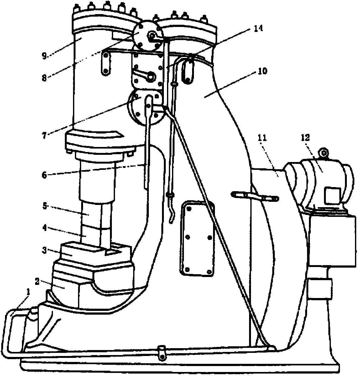
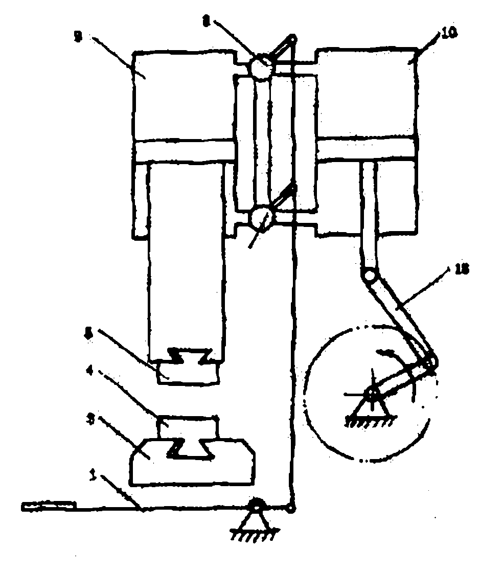
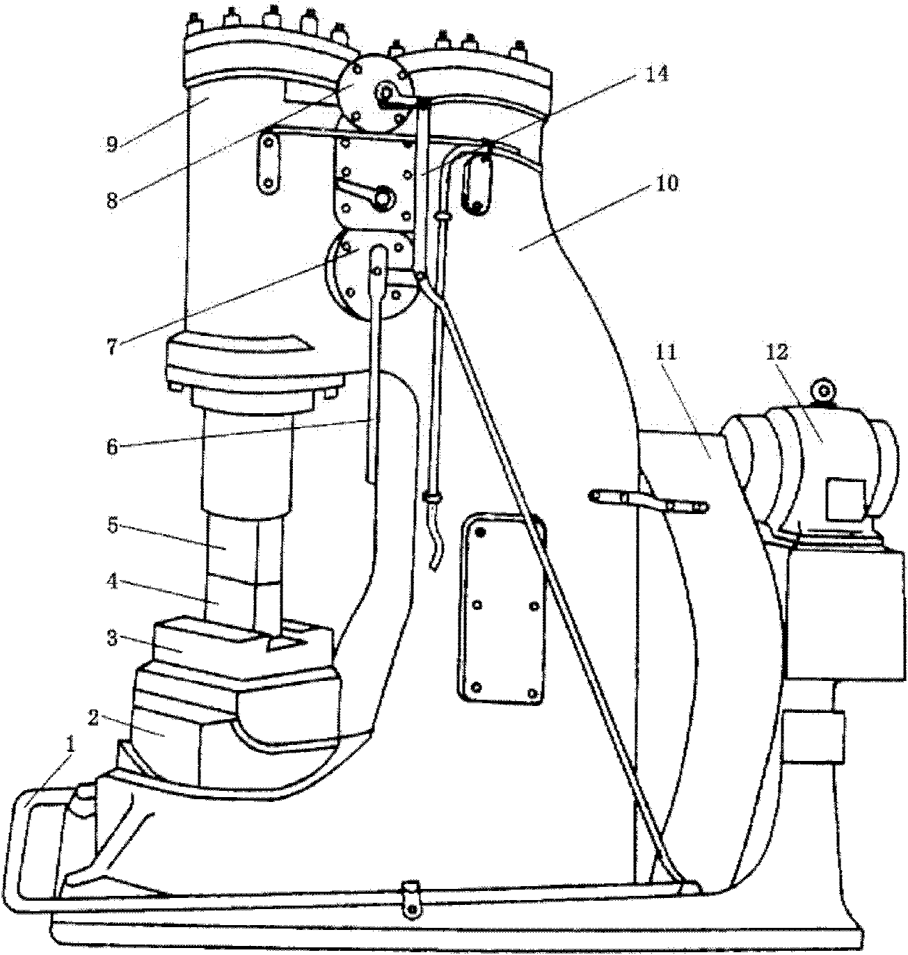
[0010] refer to figure 1 with figure 2 , The air hammer of the present invention includes a motor 12, a reducer 11, a connecting rod mechanism 13, a compression cylinder 10, a working cylinder 9 and an anvil 2. The output end of the motor 12 is connected with the reducer, the reducer 11 is connected with one end of the connecting rod mechanism, the other end of the connecting rod mechanism 13 is connected with the piston rod of the compression cylinder 10, the compression cylinder 10 and the working cylinder 9 pass through the first air pipe and The second air pipe is connected, the piston rod of the working cylinder is provided with an upper iron 5, the anvil 2 is located directly below the upper iron, and the anvil is provided with a lower iron 4, between the anvil and the lower iron 4 Anvil pad 3 is provided. It also includes a switching device for switching compressed air between the compressed air cylinder and the working cylinder, and the switching device is respectiv...


PUM


Abstract

The invention discloses an air hammer. The air hammer comprises a motor, a reducer, a connection rod mechanism, a compression air cylinder, a working air cylinder and an anvil block; the output end of the motor is connected with the reducer; the reducer is connected to one end of the connection rod mechanism; the other end of the connection rod mechanism is connected with a piston rod of the compression air cylinder; the compression air cylinder is connected with the working air cylinder through a first air transmission pipe and a second air transmission pipe; the piston rod of the working air cylinder is provided with upper pressing iron; the anvil block is positioned below the upper pressing iron, and is provided with lower pressing iron; the air hammer also comprises a switching device which can switch compressed air between the compression air cylinder and the working air cylinder; and the switching device is arranged on the first air transmission pipe and the second air transmission pipe respectively. The air hammer can suspend, continuously hammer, and press a workpiece and can also hammer the workpiece once. The air hammer can fully process the workpiece.

Description

technical field [0001] The invention relates to the technical field of forging, in particular to an air hammer. Background technique [0002] Existing air hammers are generally composed of motors, reducers, connecting rod mechanisms, compression cylinders, working cylinders and anvils. It is controlled by a rod mechanism, and there is no device for controlling compressed air between the compressed air cylinder and the working air cylinder, so that the air hammer can only achieve a single blow action. Contents of the invention [0003] In view of the above technical problems, the present invention provides an air hammer. The air hammer of the present invention can perform multiple actions such as hanging up, continuous striking, single striking and pressing down, and can perform various processing on workpieces. The technical scheme that realizes the object of the present invention is as follows: [0004] The air hammer includes a motor, a reducer, a connecting rod mechan...

Claims


Application Information

Patent Timeline
IPC IPC(8): B21J7/24
Inventor 袁正海
Owner 常州市新特力工具有限公司
Learn More