
Display device

A technology of display device and display unit, which is applied in the direction of identification device, optics, instrument, etc., and can solve the problem of not being able to have a border area.

Inactive Publication Date: 2012-05-23
SHARP KK
View PDF10 Cites 31 Cited by
  • Summary
  • Abstract
  • Description
  • Claims
  • Application Information

AI Technical Summary

Problems solved by technology

Although liquid crystal display devices are becoming narrower bezels, in principle they cannot have no bezel area

Method used


Image

  • Display device
  • Display device
  • Display device

Examples


Embodiment Construction

[0064] Hereinafter, a display device according to an embodiment of the present invention will be described with reference to the drawings, but the display device of the present invention is not limited to the following examples.

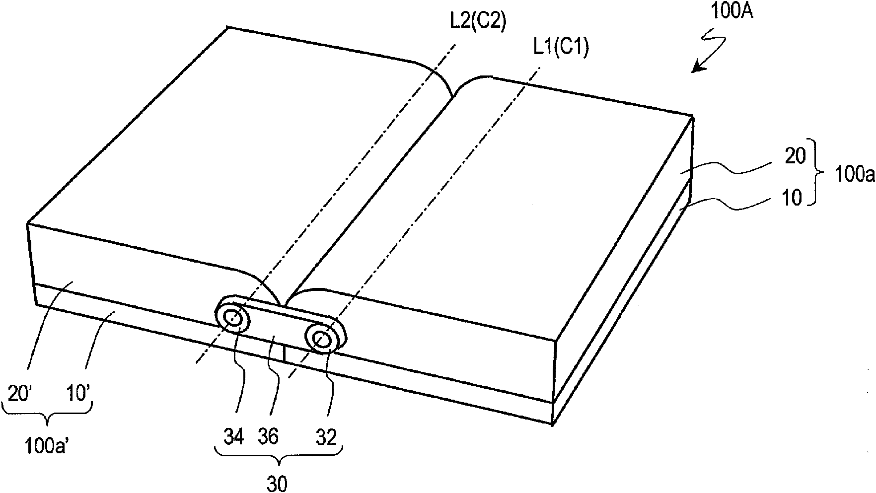
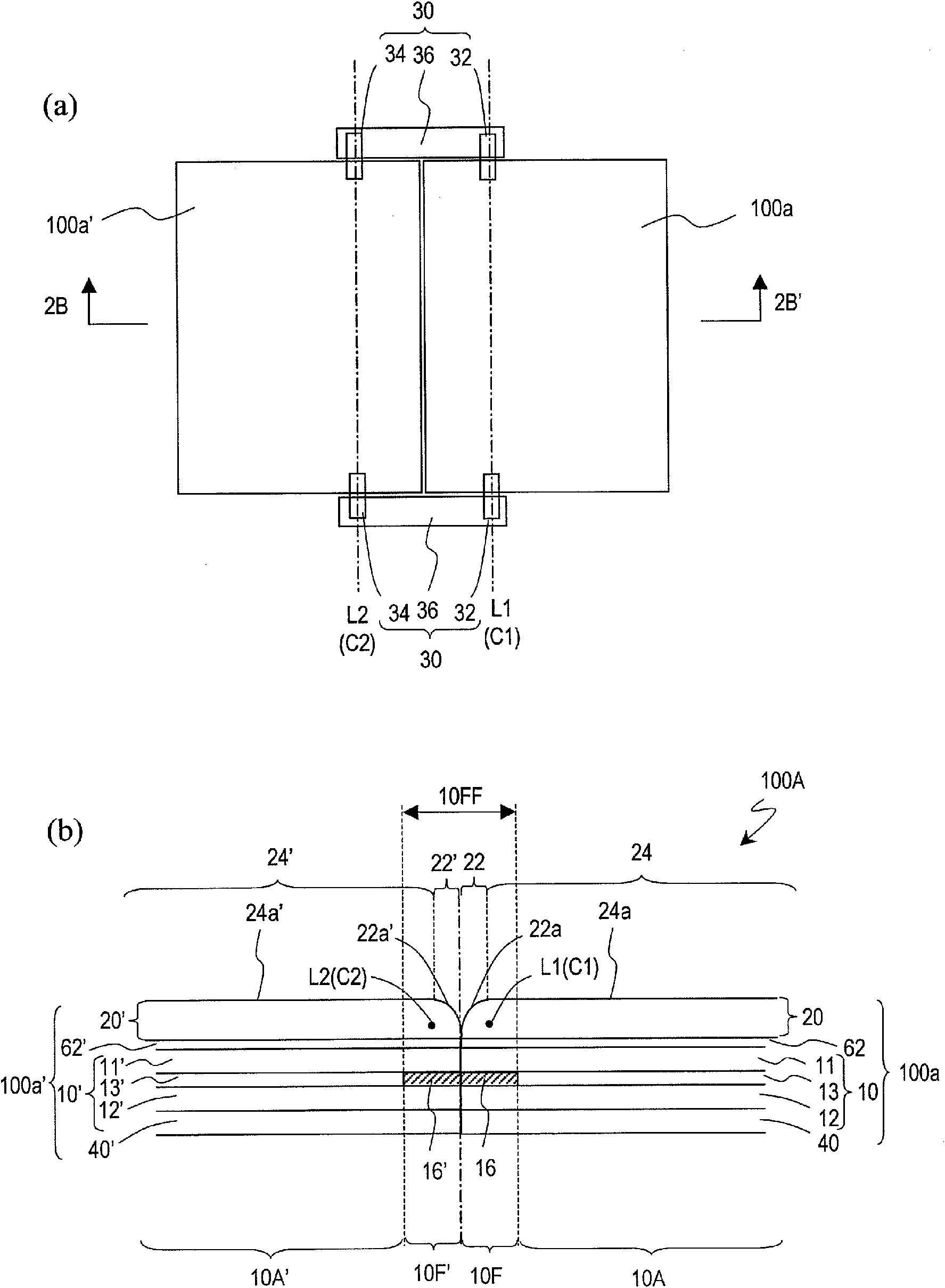
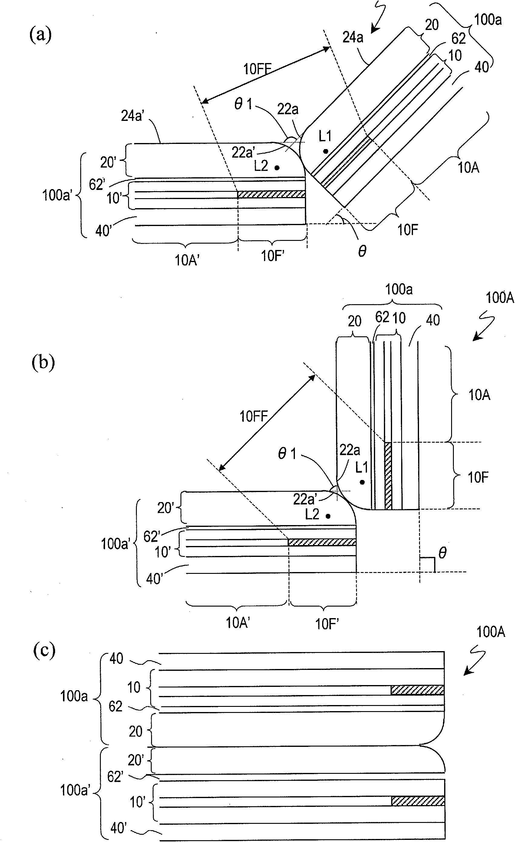
[0065] First, refer to Figure 1~3 The structure of the foldable liquid crystal display device 100A according to the embodiment of the present invention will be described.

[0066] figure 1 A schematic perspective view of the liquid crystal display device 100A is shown. figure 2 (a) shows a schematic plan view of the liquid crystal display device 100A, figure 2 (b) represents the edge figure 2 (a) A schematic cross-sectional view of the liquid crystal display device 100A along the line 2B-2B'.

[0067] Liquid crystal display device 100A, such as figure 1 As shown, there are: a liquid crystal display unit 100a, a liquid crystal display unit 100a', and a biaxial hinge device 30. Liquid crystal display device 100A, such as figure 2 As shown in (a), there ...


PUM

PropertyMeasurementUnit
refractive indexaaaaaaaaaa
compression ratioaaaaaaaaaa

Abstract

A foldable display device (100A) is provided with: first and second display units (100a, 100a'); and biaxial hinge device (30) which connects the first and second display units such that the first and second display units can rotate about first and second rotating axes (L1, L2). The first and second display units respectively have first and second display panels (10, 10') and first and second translucent covers (20, 20'). The first and second translucent covers respectively have: first and second flat plate portions (24, 24') having flat observer-side surfaces (24a, 24a'); and first and second curved surface portions (22, 22') having observer-side surfaces (22a, 22a') as parts of the columnar curved surfaces having the first and second center axes (C1, C2) as respective center axes. The first and second rotating axes of the biaxial hinge device accord with the first and second center axes. Thus, the foldable display device having a small image joint in a state between the opened state and the closed state is provided.

Description

Technical field [0001] The present invention relates to a display device, especially a direct-view type display device. Background technique [0002] The liquid crystal display device includes a liquid crystal display panel, a backlight device, a circuit for supplying various electric signals to the liquid crystal display panel, a power source, and a housing to house these. The liquid crystal display panel has a display area in which a plurality of pixels are arranged and a frame area around the display area. Pixel electrodes and TFTs are provided in the display area. A sealing part, a drive circuit mounting part, etc. are provided in the frame area. Because the pixels are not arranged in the border area, the border area does not contribute to the display. Although the liquid crystal display device is narrowing the frame, in principle, it cannot be without the frame area. [0003] When a large screen is formed by arranging a plurality of display panels, the frame area of ​​the ...

Claims


Application Information

Patent Timeline
Patent Type & Authority Applications(China)
IPC IPC(8): G09F9/00G02F1/1333G09F9/40
CPCG06F1/1681G06F1/1616G09F9/301G02F1/13336G06F1/1641G09F9/35
Inventor 渡边寿史
Owner SHARP KK
Learn More