Projection display device and method of controlling the same

A display device and projection technology, which is applied in the direction of using projection device image reproducer, projection device, picture duplicator, etc., which can solve the problems of longer operation time, complicated operation, and more operation times

Active Publication Date: 2012-05-16
SEIKO EPSON CORP
View PDF4 Cites 22 Cited by
  • Summary
  • Abstract
  • Description
  • Claims
  • Application Information

AI Technical Summary

Problems solved by technology

[0006] However, for all these configurations, the number of user operations is large, and the operations required to change the projection range are complicated.
[0007] Moreover, in the structure of Patent Document 1, it is necessary to display the operation screen, so the user cannot continue to enjoy the image.
[0008] In addition, in the structure in which the target area is operated by using the arrow keys, although there is an advantage that the user can change the desired area to the projection area, the number of operations increases accordingly, and various key operations such as up, down, left, and right are required. operation becomes complicated
In addition, sometimes it is difficult for users who are not used to remote control operations to move the target area to the center position of zoom-in or zoom-out, resulting in an increase in the number of operations and a long time required for the operation
[0009] Therefore, it is difficult to easily and quickly change to the desired projection range while continuing to enjoy the image in the existing structure.

Method used


Image

  • Projection display device and method of controlling the same
  • Projection display device and method of controlling the same
  • Projection display device and method of controlling the same

Examples


no. 1 Embodiment approach

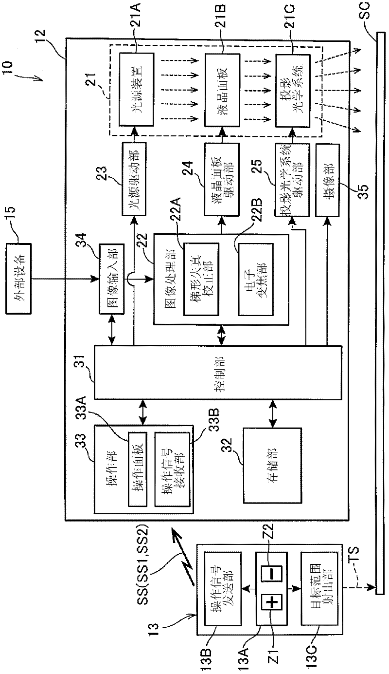
[0058] figure 1 is a diagram showing a projector (projection display device) 10 according to the first embodiment of the present invention, figure 2 is a block diagram showing the functional configuration of the projector 10 .

[0059] Such as figure 1 As shown, this projector 10 is a device that projects image light expressing an image to display an image (projected image) G0 on a screen SC as a projection surface. A remote controller (hereinafter, referred to as a remote controller) 13 for operating the projector 10 is provided.

[0060] In addition, in figure 1 For convenience of explanation, as the projected image G0, three images (the first graph image G1, the second graph image G2, and the photo image G3) are shown in the upper right, lower right, and upper left images. This image is a typical example for presentations such as product descriptions.

[0061] Such as figure 2 As shown, an image projection unit 21 constituting an optical system and an image processi...

no. 2 Embodiment approach

[0112] In the second embodiment, a configuration for realizing the same electronic zoom as in the first embodiment is described in a projector having an electronic blackboard function. Figure 9 is a diagram showing a projector (projection display device) 16 according to a second embodiment of the present invention, Figure 10 is a block diagram showing the functional configuration of the projector 16 .

[0113] Such as Figure 9 As shown, the projector 16 in this embodiment is a device that projects image light expressing an image to display an image (projected image) G0 on a screen SC as a projection surface, and includes a device main body 17 that accommodates main components and an electronic pen 18. . In addition, the projector 16 recognizes the position on the projection image G0 by recognizing the pen tip of the electronic pen 18 , draws on the projection image G0 according to the position, and performs projection. exist Figure 9 In the example shown in FIG. 2 , a ...


PUM


Abstract

A projection display device including: an image projection section configured to project an image (G0) toward a projection surface; an imaging section configured to shoot the image (G0) projected on the projection surface; a location specifying section configured to specify a location of a position indication light based on a shot image by the imaging section; and a display control section configured to set a projection range of the image to a range including an image area (Ar1) corresponding to the location specified by the location specifying section, and to alter the projection range of the image in accordance with the set projection range.

Description

technical field [0001] The present invention relates to a projection display device capable of changing the size of a projected image and a control method thereof. Background technique [0002] Among projection display devices (projectors), some projection display devices have a function (so-called electronic zoom function) that uses image processing to change the projection range without using a lens, so that the image projected on the projection surface is enlarged or zoomed in. zoom out. [0003] For a projection type display device having such an electronic zoom function, the following scheme has been proposed: an operation screen (OSD image (On-Screen Display: On-Screen Display) is displayed, and the user operates keys in the operation screen to select a zoom-in (wide) Or zoom out (far) to change to an enlarged or reduced projection range (for example, refer to Patent Document 1). [0004] In addition, in some projection-type display devices circulating in the market,...

Claims


Application Information

Patent Timeline
Patent Type & Authority Applications(China)
IPC IPC(8): G03B21/00G03B17/54G03B21/14H04N5/74G03B30/00G06F3/048G06F3/0484
CPCG06F3/03542H04N9/3185G06F3/04817G03B21/006H04N5/74G06F3/0304G06F3/017G06F3/04842H04N9/31G06F3/04845G03B21/14G06F2203/04806G06F3/0386
Inventor 小泽孝明
Owner SEIKO EPSON CORP
Why Eureka
Try Eureka