Liquid detection chip and liquid detection method
A detection chip and detection method technology, applied in the direction of measuring devices, color/spectral characteristic measurement, material analysis through electromagnetic means, etc., can solve the problems of inability to calibrate on-site, poor accuracy, etc., to ensure accuracy and reliability, and flexibility Effects of transformations and upgrades
- Summary
- Abstract
- Description
- Claims
- Application Information
AI Technical Summary
Problems solved by technology
Method used
Image
Examples
Embodiment 1
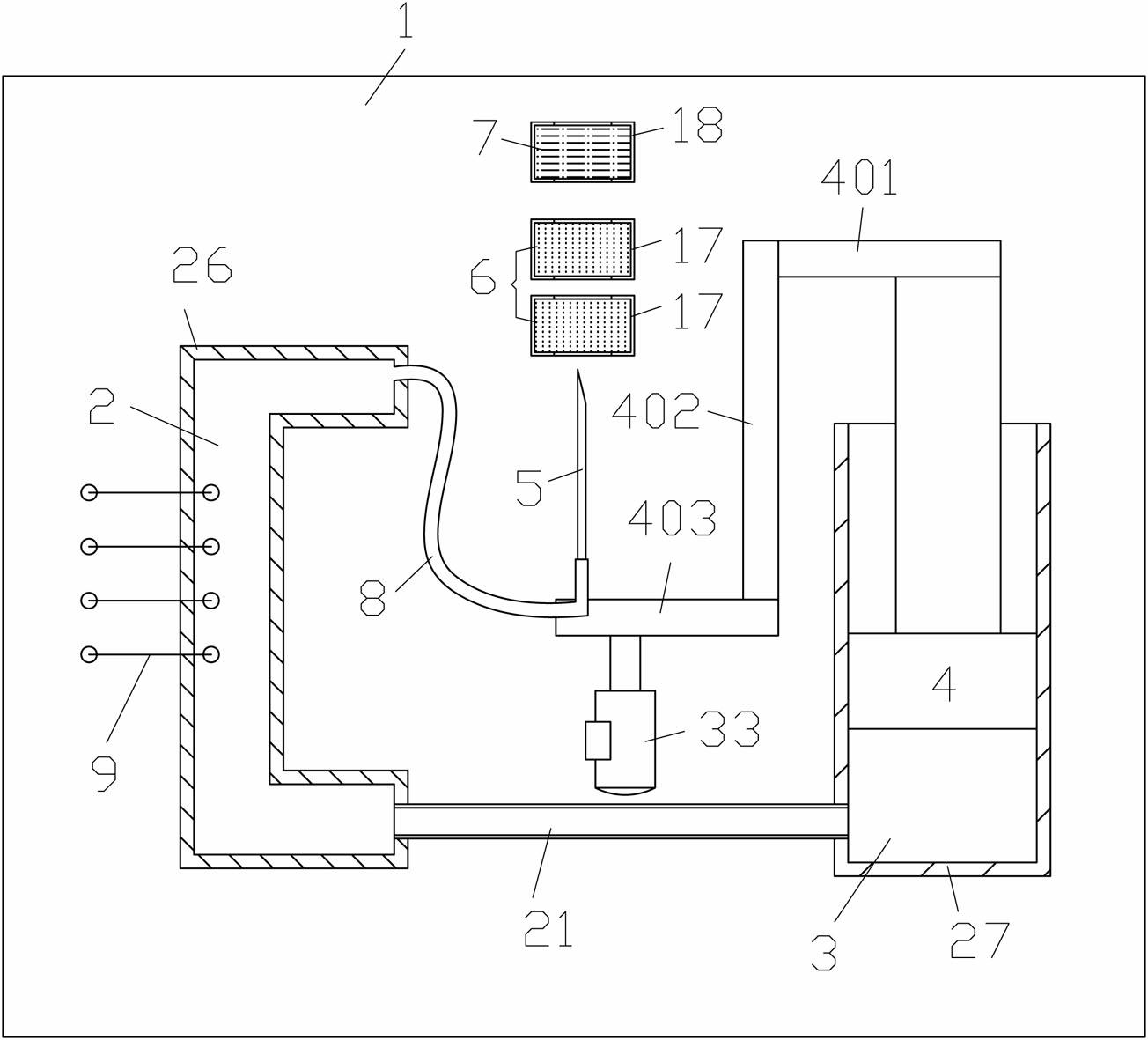
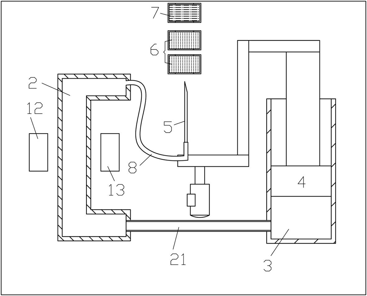
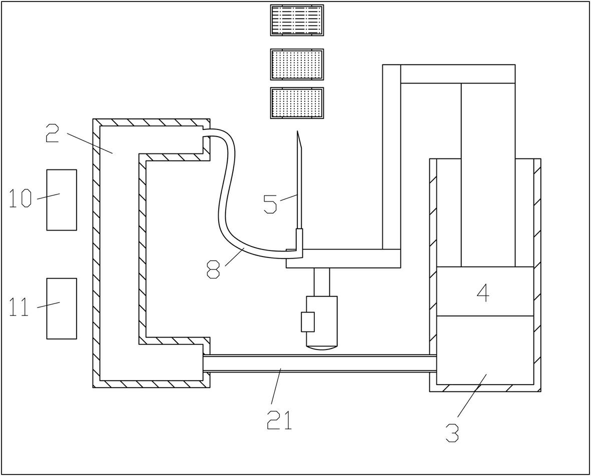
[0111] Embodiment 1, see attached figure 1 , 2 , 3, 4, 5, 6, 7, 8, 9, 10, a liquid detection chip, including a base 1, the base 1 is generally made of rigid materials, which can be plastic or metal, and the base 1 is provided with Measuring pool 2, waste liquid chamber 3, in this embodiment, measuring pool 2 is located in the boss 26 that is arranged on the base, waste liquid chamber 3 is located in the cylinder 27 on the base, and measuring pool 2 is to measure the measured liquid One of the functions of the waste liquid chamber 3 is to store the detected liquid to prevent the detected liquid from being discharged to pollute the environment, and the other is to generate vacuum suction. Therefore, a piston 4 is installed in the waste liquid chamber 3 with a clearance fit. , in order to increase the sealing performance of the piston and the waste liquid chamber, and also in order to make the movement of the piston more smooth, the outer surface of the piston 4 is coated with l...
Embodiment 2
[0132] Embodiment 2, see attached Figure 11 , The difference between this embodiment and Example 1 is that there is one test liquid package 7 and one calibration package 6 set on the base 1 .
[0133] Its detection method is:
[0134] a) Preparatory step: placing the detection chip in the detection instrument, and then setting a calibration package 6 and a tested liquid package 7 on the base 1;
[0135] b) Calibration package detection step: push the piston 4 to move forward in the waste liquid chamber 3, so that a negative pressure is formed in the waste liquid chamber 3 to generate suction. When the hollow sampling needle 5 pierces the calibration package 6, the calibration package 6 The calibration liquid enters the measuring pool 2 through the capillary tube 8, and after being detected by the detection device, the result is sent to the signal processing unit of the detection instrument in the form of an electrical signal to obtain a calibrated detection result, and the d...
Embodiment 3
[0139] Embodiment 3, see attached Figure 12 The only difference between this embodiment and Embodiment 1 is that, in this embodiment, there is one liquid package to be tested and three calibration packages arranged on the base.
[0140] Its detection method is;
[0141]a) Preparatory step: place the detection chip in the detection instrument, and then set three calibration packages 6 and one test liquid package 7 on the base 1, the distance between the calibration package and the hollow sampling needle is from close to The calibration accuracy corresponding to the calibration liquid in the calibration package is arranged in order from high to low.
[0142] b) Calibration bag detection step: push the piston 4 to move forward in the waste liquid chamber 3, so that a negative pressure is formed in the waste liquid chamber 3 to generate suction, and when the hollow sampling needle 5 pierces three calibration bags 6 in sequence, the calibration bag 6 The calibration liquid insid...
PUM
 Abstract
Description
Claims
Application Information
 - Generate Ideas
- Intellectual Property
- Life Sciences
- Materials
- Tech Scout
- Unparalleled Data Quality
- Higher Quality Content
- 60% Fewer Hallucinations
Browse by: Latest US Patents, China's latest patents, Technical Efficacy Thesaurus, Application Domain, Technology Topic, Popular Technical Reports.
© 2025 PatSnap. All rights reserved.Legal|Privacy policy|Modern Slavery Act Transparency Statement|Sitemap|About US| Contact US: help@patsnap.com


