
Optical color sensing system and optical color sensing device using same

An optical sensing and color technology, applied in the field of measuring the optical properties of samples or materials, can solve the problems of color detection interference, poor color detection stability, easy to be interfered by the external environment, etc., to reduce misjudgment results, eliminate interference, improve The effect of efficiency

Active Publication Date: 2012-05-02
福州泰普生物科学有限公司
View PDF7 Cites 1 Cited by
  • Summary
  • Abstract
  • Description
  • Claims
  • Application Information

AI Technical Summary

Problems solved by technology

[0002] At present, the current color sensors directly read the surface color of the measured object through the integrated color sensor chip, and the relatively close colors cannot be effectively distinguished at all, and are easily disturbed by the external environment. different and cannot be effectively used for practical use
[0003] The color sensors made on the existing market need to place the measured object very close to the chip of the sensor, and also require independent white light and white light calibration. White light contains light of different wavelengths and colors. When detecting very subtle color differences, these light It will interfere with color detection, resulting in poor stability of color detection

Method used


Image

  • Optical color sensing system and optical color sensing device using same
  • Optical color sensing system and optical color sensing device using same
  • Optical color sensing system and optical color sensing device using same

Examples


Embodiment Construction

[0029] In order to describe the technical content, structural features, achieved goals and effects of the present invention in detail, the following will be described in detail in conjunction with the embodiments and accompanying drawings.

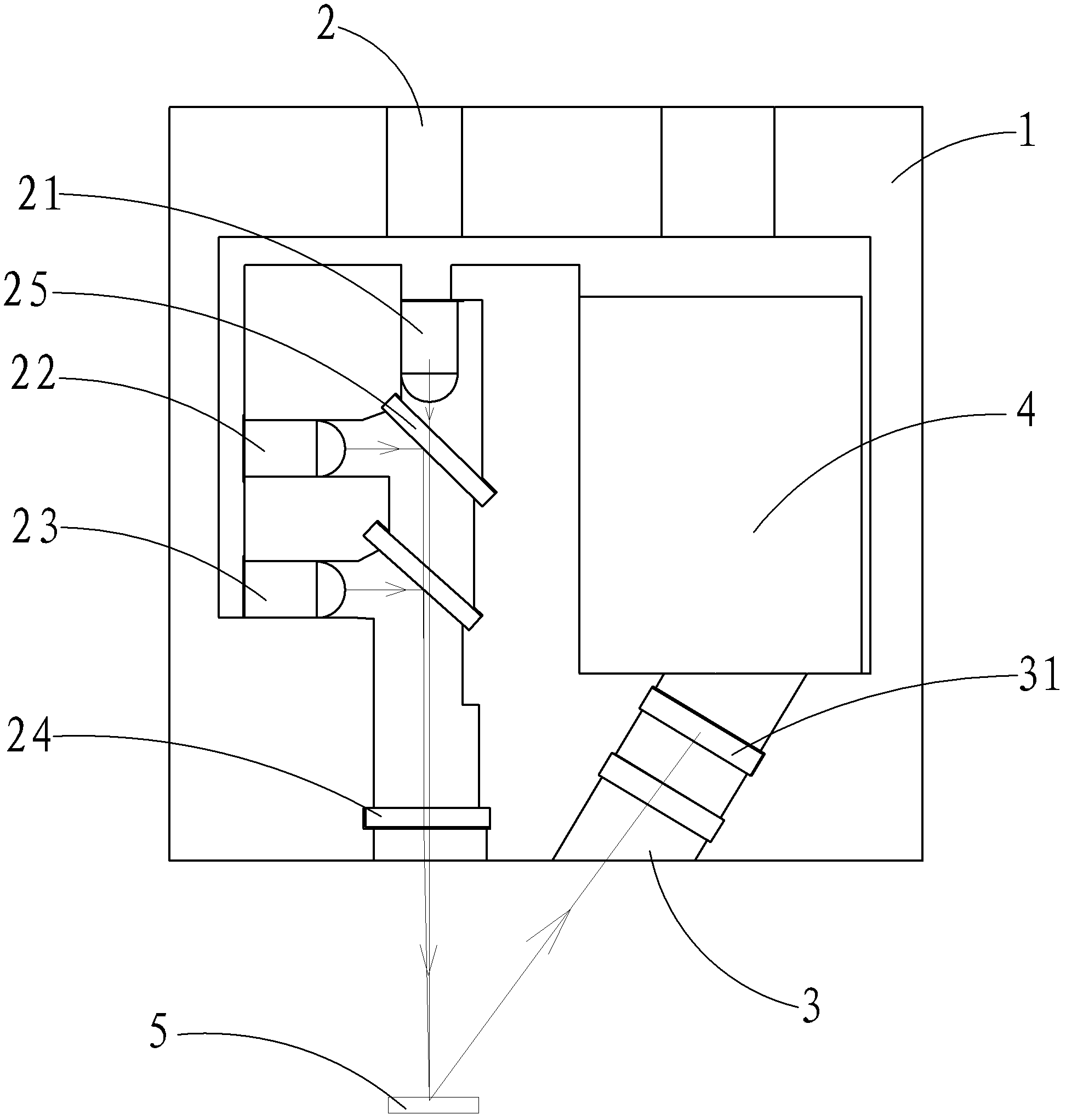
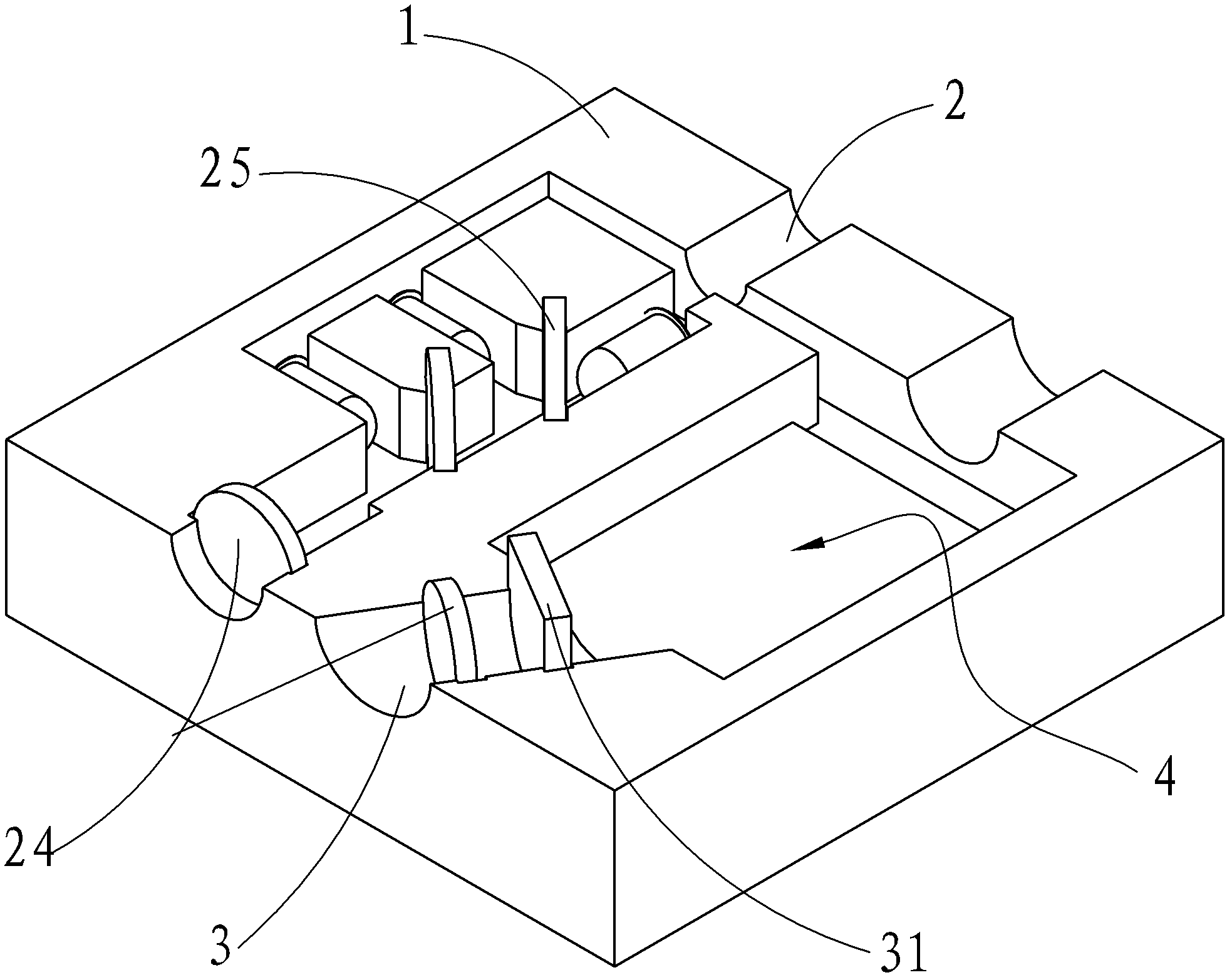
[0030] Please also refer to figure 1 and figure 2 , as shown in the figure, the embodiment of the present invention includes a fixed base 1 , an emission source line channel 2 , a light receiving channel 3 and a color processing device 4 arranged on the fixed base 1 .

[0031] A certain angle is set between the emission source line channel 2 and the light receiving channel 3, and the angle is set according to the angle at which the light emitted by the emission source line channel 2 is reflected on the surface of the color to be inspected, so that the reflected light can accurately enter the light receiving channel For channel 3, the inventors found that setting the inner angle between source line channel 2 and light receiving channel 3 ...


PUM


Abstract

The invention discloses an optical color sensing system. Emission lights for detecting a color are generated by three primary color emission sources and the three primary color emission sources comprise a green light emission source, a red light emission source and a blue light emission source; a collector lens is arranged along the direction of an emission light path and the emission lights are collected into a bunch of lights through the collector lens to emit toward a surface with the color to be detected; the lights are reflected by the surface with the color to be detected; and a collector lens is arranged along the direction of a reflection light path and the reflected lights are gathered to a light receiver through the collector lens. The optical color sensing system and the optical color sensing device using the same, provided by the invention, have the beneficial effects that: the lights which are sent by the three primary color emission sources are gathered together to replace a white light source, so as to effectively remove interference of other lights and more flexibly reflect the color of a detected object; by applying the optical color sensing device to a vaginopathy detection system, the color of a coloration dot of a sample can be more really distinguished and an artificial visual colorimetry is replaced, so that not only is the efficiency improved, but also misjudged results caused by artificial careless and the like can be reduced.

Description

technical field [0001] The invention relates to measuring the optical properties of samples or materials, in particular to a color optical sensing device for measuring the color of samples or materials. Background technique [0002] At present, the current color sensors directly read the surface color of the measured object through the integrated color sensor chip, and the relatively close colors cannot be effectively distinguished at all, and are easily disturbed by the external environment. different and cannot be effectively used in practical use. [0003] The color sensors made in the existing market need to place the measured object very close to the chip of the sensor, and also need independent white light and white light calibration. White light contains light of different wavelengths and colors. When detecting very subtle color differences, these light It will interfere with the color detection, resulting in poor stability of color detection. Contents of the inven...

Claims


Application Information

Patent Timeline
Patent Type & Authority Applications(China)
IPC IPC(8): G01J3/46
Inventor 陈坚李政蔡玉明胡守旺谢佐福周晓强姚铭锋林滨
Owner 福州泰普生物科学有限公司
Learn More