Wheel arranging device for steel cord outer winding machine and wheel arranging method thereof

A technology of outer winding machine and steel cord, which is applied in the direction of hoisting device, transportation and packaging, spring mechanism, etc., and can solve the problems of affecting production efficiency, heavy weight, slipping and bruising, etc.

Active Publication Date: 2013-06-12
HENAN HENGXING SCIENCE & TECHNOLOGY CO LTD
View PDF8 Cites 0 Cited by
  • Summary
  • Abstract
  • Description
  • Claims
  • Application Information

AI Technical Summary

Problems solved by technology

[0002] In the prior art, the operator of the steel cord outer winding machine needs to pick up the I-shaped wheel with a steel wire at a height of more than one meter when loading the I-shaped wheel, and install it on the pay-off shaft. Because the steel wire and the I-shaped wheel The weight of the wheel itself is relatively heavy, and it is difficult for some thin-bodied start-up personnel to carry it up, requiring the cooperation of two people. In addition, because it is carried by hand, it is more dangerous and prone to slipping and injury accidents, which indirectly affects production efficiency.

Method used


Image

  • Wheel arranging device for steel cord outer winding machine and wheel arranging method thereof
  • Wheel arranging device for steel cord outer winding machine and wheel arranging method thereof

Examples


Embodiment 1

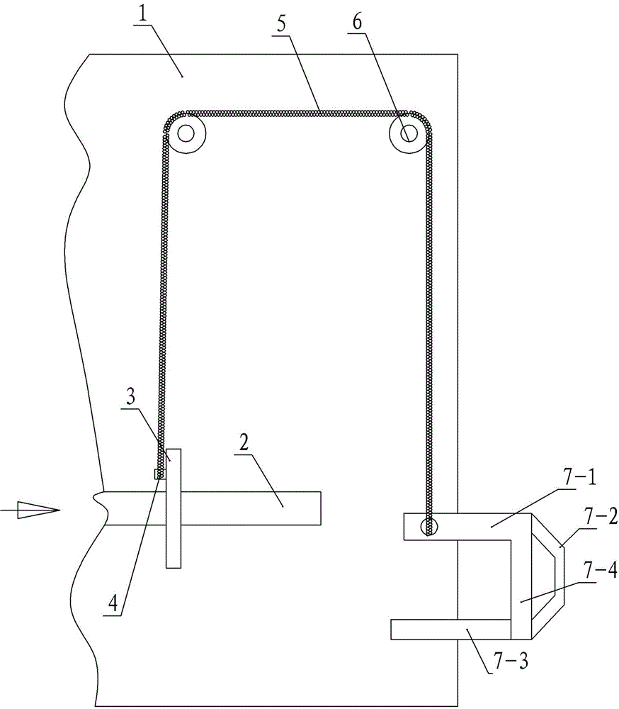
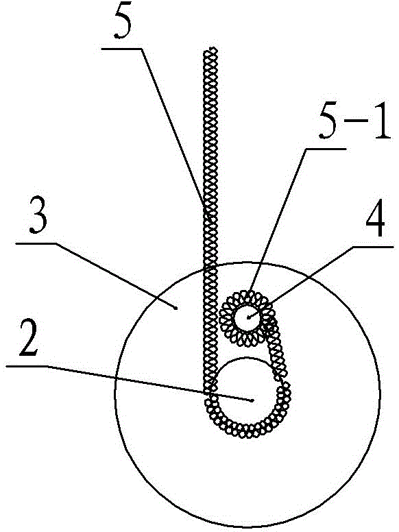
[0019] Embodiment one: see figure 1 , figure 2 , a steel cord outer winding machine upper wheel device in the figure, including the steel cord outer winding machine's own pay-off shaft and two guide wheels on the upper part of the pay-off shaft, the pay-off shaft is connected with the power unit, and the pay-off A reel is provided on the shaft, and a hook is provided on the reel. The upper wheel device also includes a flexible suspension rope and a wheel fork. One end of the flexible suspension rope is connected to the wheel fork, and the other end is provided with a rope sleeve. , the rope sleeve is hung on the hook on the reel, and the middle part of the flexible sling is hung on the two upper guide wheels. The wheel fork includes an inner rod and an outer rod, the ends of both sides are connected by a vertical rod, and a handle is provided on the outside of the vertical rod; the end of the flexible suspension rope is connected to the outer rod. Of the two guide wheels, o...

Embodiment 2

[0020] Embodiment two: see figure 1 , figure 2 , a method for loading wheels on a steel cord outer winding machine, the steel cord outer winding machine is provided with a pay-off shaft and two guide wheels on the upper part of the pay-off shaft, the pay-off shaft is connected with a power unit, and the pay-off shaft is Provided with a reel, the method also requires a fork and a flexible sling, comprising the following steps,

[0021] ①. Insert the wheel fork into the shaft hole of the I-shaped wheel first, then connect one end of the flexible sling to the wheel fork, and the other end of the flexible sling to the reel, and finally put the middle of the flexible sling on the on the two guide wheels;

[0022] ②. Start the power device of the steel cord outer winding machine, drive the pay-off shaft to rotate, drive the winding wheel to rotate, and gradually wind the flexible sling on the anti-spool, so that the wheel fork and the I-shaped wheel connected to the other end of ...


PUM


Abstract

The invention discloses a wheel arranging device for a steel cord outer winding machine and a wheel arranging method thereof. The wheel arranging device comprises a paying-off shaft of the steel cord outer winding machine per se, two guide wheels, a flexible hanging rope and a wheel fork, wherein the two guide wheels are arranged on the upper part of the paying-off shaft; the paying-off shaft is connected with a power device, and is provided with a winding wheel; the winding wheel is provided with a hook; one end of the flexible hanging rope is connected to the wheel fork, and the other end of the flexible hanging rope is provided with a rope sleeve; the rope sleeve is hung on the hook on the winding wheel; and the middle part of the flexible hanging rope is overlapped on the two guide wheels on the upper part. Due to the adoption of the device and the wheel arranging method, the labor intensity of starting personnel is lowered, the wheel arranging efficiency is increased without requiring cooperation of two persons basically, accidents of crashing injury are avoided, and the starting difficulty is lowered.

Description

technical field [0001] The invention relates to the technical field of tool accessories of a steel cord outer winding machine, in particular to a steel cord outer winding machine upper wheel device and a wheel upper method. Background technique [0002] In the prior art, the operator of the steel cord outer winding machine needs to pick up the I-shaped wheel with a steel wire at a height of more than one meter when loading the I-shaped wheel, and install it on the pay-off shaft. Because the steel wire and the I-shaped wheel The weight of the wheel itself is relatively heavy, and it is difficult for some thin-bodied start-up personnel to carry it up, requiring the cooperation of two people. In addition, because it is carried by hand, it is more dangerous and prone to slipping and injury accidents, which indirectly affects production efficiency. Contents of the invention [0003] The object of the present invention is to solve the above-mentioned problems, and to provide...

Claims


Application Information

Patent Timeline
Patent Type & Authority Patents(China)
IPC IPC(8): B66D1/60B66C1/62
Inventor 曲旭东李成立逯胜利焦金州
Owner HENAN HENGXING SCIENCE & TECHNOLOGY CO LTD
Why Eureka
Try Eureka