
Spherical workpiece placement device

A workpiece and spherical technology, which is applied in the field of spherical workpiece shelving devices, can solve problems such as displacement, personal injury, and easy rolling, and achieve the effects of simple device structure, improved production safety, and convenient processing

Inactive Publication Date: 2012-05-02
CHENGDU KESHENG PETROLEUM TECH +1
View PDF5 Cites 2 Cited by
  • Summary
  • Abstract
  • Description
  • Claims
  • Application Information

AI Technical Summary

Problems solved by technology

These spherical workpieces are easy to roll and shift during stacking or storage; especially for some large spherical workpieces, it is easy to cause injury to personnel during the rolling process

Method used


Image

  • Spherical workpiece placement device
  • Spherical workpiece placement device
  • Spherical workpiece placement device

Examples


Embodiment 1

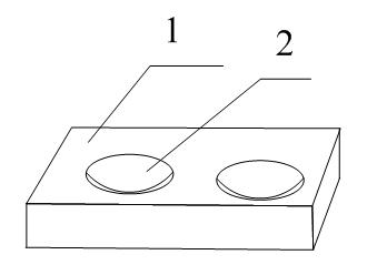
[0024] Such as figure 1 As shown, the spherical workpiece resting device includes a base 1 on which a hemispherical recess 2 is provided.

[0025] Preferably, the number of the recesses is two, and the upper surface of the recesses 2 is provided with patterns.

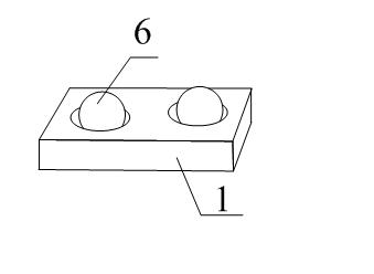
[0026] In use, the spherical workpiece is placed in the hemispherical recess. The two are attached to each other, so displacement is not easy to occur; that is, the spherical workpiece can be restricted in a certain position.

Embodiment 2

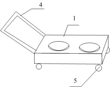
[0028] The basic structure of this embodiment is the same as that of Embodiment 1, the difference is that casters 5 are provided under the base, and a push handle 4 is provided on one side of the base.

[0029] The setting of the casters and the push handle can facilitate the handling of the workpieces stored on the spherical workpiece shelving device.

[0030] During specific implementation, gauze may also be laid on the upper surface of the concave portion.


PUM


Abstract

The invention discloses a spherical workpiece placement device which comprises a base (1), wherein the base is provided with hemispherical dents (2). Spherical workpieces can be limited in the hemispherical dents, thereby implementing located placement of the spherical workpieces. Caster wheels and a push grip are arranged, so that more than one spherical workpiece can be simultaneously transported, thereby saving both labor and time.

Description

technical field [0001] The invention relates to the field of mechanical equipment, in particular to a spherical workpiece resting device. Background technique [0002] During the production and processing of petroleum equipment, spherical workpieces are often involved. These spherical workpieces are easy to roll and shift during stacking or storage; especially for some large spherical workpieces, it is easy to cause injury to personnel during the rolling process. Therefore, it is necessary to design a spherical workpiece resting device for positioning and storing spherical workpieces at fixed points. Contents of the invention [0003] The technical problem to be solved by the device of the present invention is to provide a spherical workpiece resting device, which can position and store the spherical workpiece; and has a simple structure, convenient processing, and easy popularization and application. [0004] The technical solution adopted by the device of the present i...

Claims


Application Information

Patent Timeline
Patent Type & Authority Applications(China)
IPC IPC(8): B25H5/00
Inventor 贺昶明
Owner CHENGDU KESHENG PETROLEUM TECH
Learn More