Detection method for rotation speed of roller of washing and dehydration machine and detection unit structure thereof

A drum rotation speed and detection method technology, applied in the direction of linear/angular velocity measurement, velocity/acceleration/impact measurement, measuring device, etc., can solve problems such as poor adaptability, affecting the performance and life of the washer-extractor, and achieve stable operation maintenance, Achieve quick response and reduce washing energy consumption

Inactive Publication Date: 2012-04-25
JIANGSU SEA LION MASCH GRP CO LTD
View PDF4 Cites 0 Cited by
  • Summary
  • Abstract
  • Description
  • Claims
  • Application Information

AI Technical Summary

Problems solved by technology

[0004] Based on the drum drive structure, the existing washer-extractor has relatively poor adaptability to load differences, which will affect the performance and life of the washer-extractor for a long time

Method used


Image

  • Detection method for rotation speed of roller of washing and dehydration machine and detection unit structure thereof
  • Detection method for rotation speed of roller of washing and dehydration machine and detection unit structure thereof
  • Detection method for rotation speed of roller of washing and dehydration machine and detection unit structure thereof

Examples


Embodiment 1

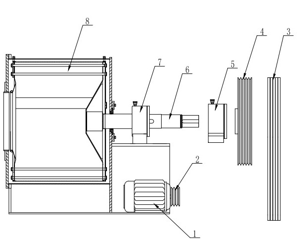
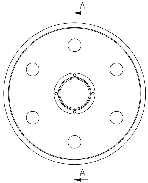
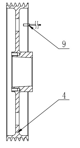
[0024] like Figure 2a and Figure 2b As shown, six load-relief holes are evenly distributed on the circumference of the wheel surface of the large pulley 4, and the speed sensor 9 is installed in the air relative to the wheel surface, and coincides with the circle formed by the center of the load-relief holes on the large pulley. When rotating, a pulse signal proportional to the rotational speed is generated between the rotational speed sensor and the wheel surface due to the relative movement of the unloading hole.

[0025] Although the number of load-relief holes in this embodiment is six, in the actual application process, the number can be set arbitrarily according to actual needs, generally more than two, and these load-relief holes are coaxial and evenly distributed on the circumference driven wheel face.

Embodiment 2

[0027] like Figure 3a and Figure 3b As shown, on the central shaft 6, there is a keyway with a concave opposite surface, and the sensor is installed on the axial center plane of the keyway close to the shaft surface. When the central shaft 6 rotates, the gap between the speed sensor and the shaft surface is due to The keyway changes, and a pulse signal proportional to the shaft speed is obtained.

[0028] Through the above overview, detailed description and embodiment introduction in conjunction with the accompanying drawings, the features of the detection method and its detection unit structure of the present invention should have been fully demonstrated and easy to understand. And implementing the technical scheme of the present invention, its significant technical progress is reflected in: provide the real-time detection input for the real-time control of washing machine, can solve the motor stall that load changes cause, realize the fast response of forward and reverse ...


PUM


Abstract

The invention discloses a detection method for rotation speed of a roller of a washing and dehydration machine and a detection unit structure thereof. Real-time detection is performed on the rotation speed during washing, uniform distribution and intermediate-speed and high-speed dehydration; based on an electromagnetic induction principle, the rotation speed of the roller of the washing and dehydration machine can be detected in real time by capturing and detecting variation in an electric signal caused by rotation or movement of a metal body and is provided to a controller as a modulation signal source for output control. By implementing the detection method and the detection unit structure provided by the invention, real-time detection input is provided for real-time control of the washing and dehydration machine; and thus, motor stall caused by load variation can be solved, quick response to switching of positive and negative rotation is realized, stable operation of the machine is maintained, the washing efficiency of linen is increased, the washing time is shortened, and the washing energy consumption is reduced.

Description

technical field [0001] The invention relates to a real-time control method of an washer-extractor, in particular to a detection method and a detection structure of a drum rotation speed of the washer-extractor, and belongs to the field of electromechanical control. Background technique [0002] At present, the washing machine still generally adopts a fixed programmed operation mode. Under the set motor speed, the difference in load during washing and dehydration will easily cause the stall of the motor, which will seriously affect the performance stability and service life of the motor and transmission belt. At the same time, the switching of the positive and negative rotation of the washing drum needs to be carried out after the drum stops. In order to ensure safety and prolong the service life of the motor, the stop delay time during switching is longer, which exceeds the actual stop time, prolonging the washing and dehydration time . [0003] Traditional washer-extracto...

Claims


Application Information

Patent Timeline
Patent Type & Authority Applications(China)
IPC IPC(8): G01P3/481
Inventor 陆亚琳颜岗黄苏鸣冯宇丁雨峰
Owner JIANGSU SEA LION MASCH GRP CO LTD
Why Eureka
Try Eureka