
Fixing structure of shield electric wire and fixing method for shield electric wire

A technology for fixing structures and wires, applied in the direction of protective grounding/shielding devices, circuits, electrical components, etc. of connecting parts, which can solve the problem that shielded connectors cannot be used, achieve a stable and reliable connection state, and avoid distortion or deformation.

Active Publication Date: 2012-04-18
YAZAKI CORP
View PDF13 Cites 12 Cited by
  • Summary
  • Abstract
  • Description
  • Claims
  • Application Information

AI Technical Summary

Problems solved by technology

Therefore, depending on the kind of shielded electric wires for the vehicles on which the shielded electric wires are respectively installed, or the difference in the shielding process for the vehicles on which the shielded electric wires are respectively mounted (that is, individual shielding processing and concentrated The difference between the shielding treatment, etc.), this shielded connector is sometimes not applicable

Method used


Image

  • Fixing structure of shield electric wire and fixing method for shield electric wire
  • Fixing structure of shield electric wire and fixing method for shield electric wire
  • Fixing structure of shield electric wire and fixing method for shield electric wire

Examples


Embodiment Construction

[0046] Exemplary embodiments of the present invention will be described in detail below with reference to the accompanying drawings.

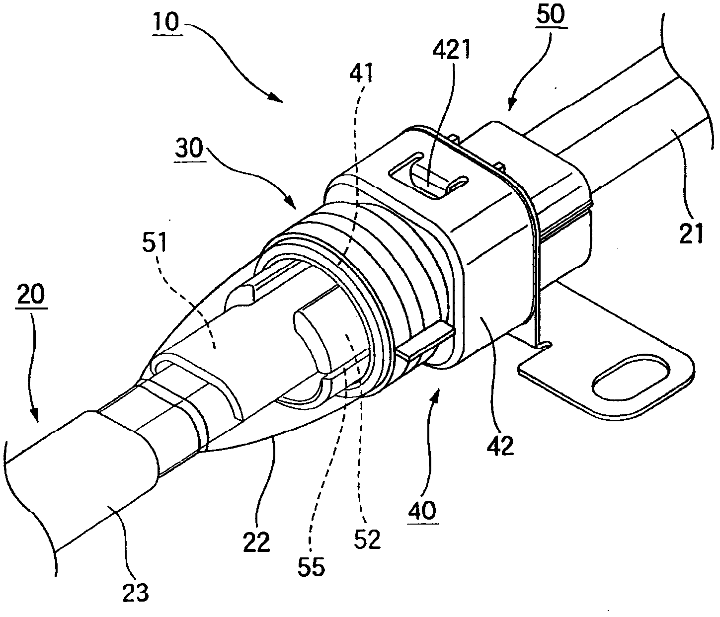
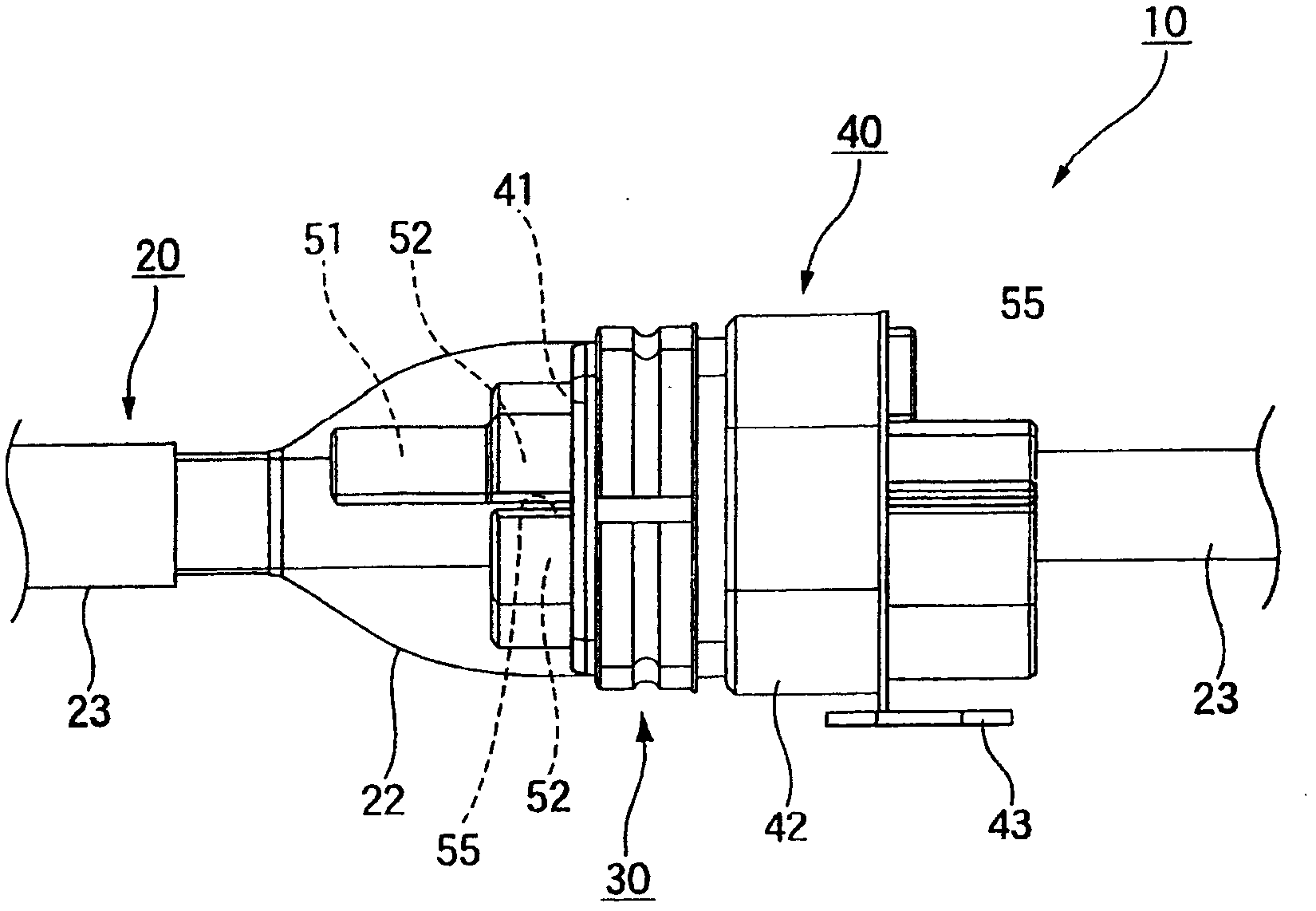
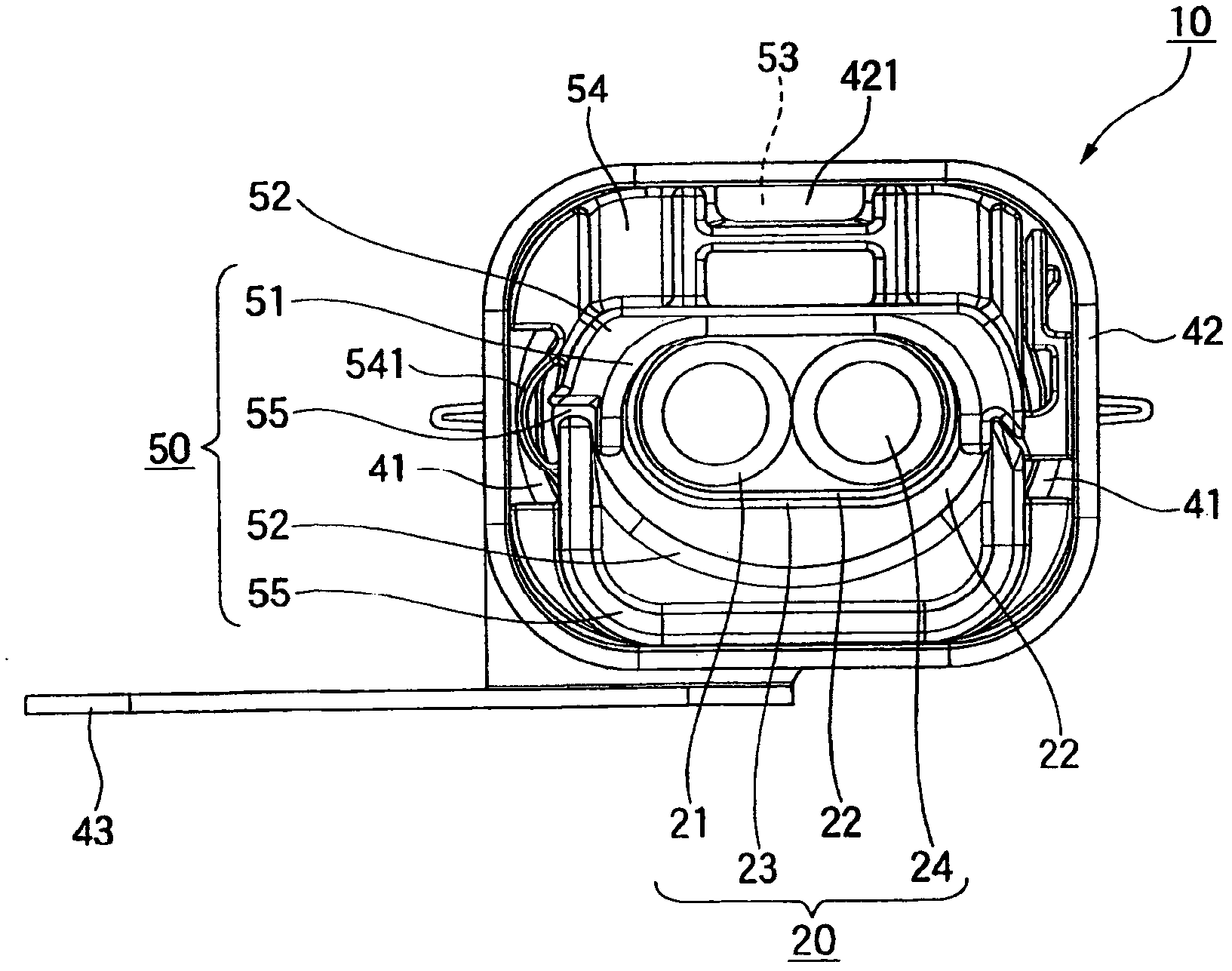
[0047] Figures 1 to 3 A fixing structure 10 of a shielded electric wire according to an exemplary embodiment of the present invention is shown. The fixing structure 10 of the shielded wire comprises a shielded wire 20, a shield ring 30, a shield shell 40 and an inner holder 50 (in image 3 , the shielding ring 30 is shown in the state before the shielding ring is clamped).

[0048] The shielded electric wire 20 includes: a core wire 24 at a central portion; an insulating coat 21 formed of an insulating material such as an insulating resin for coating the outer periphery of the core wire 24; a conductive braided portion 22; and an insulating sheath 23 for covering the outer side of the braided portion 22. The shielded electric wire 20 of this exemplary embodiment has a structure in which core wires of two cores are shielded together. Howeve...


PUM


Abstract

A fixing structure includes: a shield electric wire; a shield shell having a small diameter part having a hollow tubular-shape through which the exposed part passes, and an outer periphery being covered with an end of a peeled braided part of the shield electric wire, and a main body part having a hollow shape extended from the small diameter part and through which the shield electric wire passes; a shield ring clamped to the small diameter part under a state that the end of the peeled braided part is located between the shield ring and the small diameter part; and an inner holder that is inserted into and fixed to an inner part of the main body part under a state that the shield electric wire passes through the inner holder.

Description

technical field [0001] The invention relates to a fixing structure for connecting shielded electric wires to a shielding shell and a fixing method for shielding electric wires. Background technique [0002] Among shielded electric wires used for power supply lines or wiring of various vehicles such as hybrid cars, as shielded connectors connected to terminals thereof, for example, a shielded connector disclosed in Patent Document 1 is known. [0003] That is, shielded connectors are used in wiring of vehicle electrical systems. Such as Figure 13 As shown, the shielded connector 100 includes a connector post 120 connected to the terminal portion of the shielded electric wire 110 having a core wire 111, a braided portion 112 and an armor 113; connector housing 130; corrugated holder 140 connected to the wire insertion side of connector housing 130; The wire insertion side of the device housing 130. The corrugated holder 140 is formed from a pair of opposing half-covers. ...

Claims


Application Information

Patent Timeline
Patent Type & Authority Applications(China)
IPC IPC(8): H01R9/03
CPCH01R13/6582H01R13/512H01R13/658H01R13/506H01R9/038H01R9/0518H01R13/6593H01R13/65918
Inventor 出野正博津岛義高
Owner YAZAKI CORP
Learn More