
Pneumatic two-position four-way reversing valve

A two-position four-way, reversing valve technology, used in multi-way valves, valve details, valve devices, etc.

Inactive Publication Date: 2012-04-18
CHONGQING CHANGJIANG COATING EQUIP
View PDF10 Cites 7 Cited by
  • Summary
  • Abstract
  • Description
  • Claims
  • Application Information

AI Technical Summary

Problems solved by technology

The two-position four-way reversing valve built into the existing air motor will stop at the "dead point" position during operation, that is, the air intake chamber of the air distribution chamber is directly connected to the exhaust port through the slider, causing the sprayer to stop work, it is strictly forbidden for the spraying machine to appear "dead spot" phenomenon on the automatic spraying line

Method used


Image

  • Pneumatic two-position four-way reversing valve
  • Pneumatic two-position four-way reversing valve

Examples


Embodiment Construction

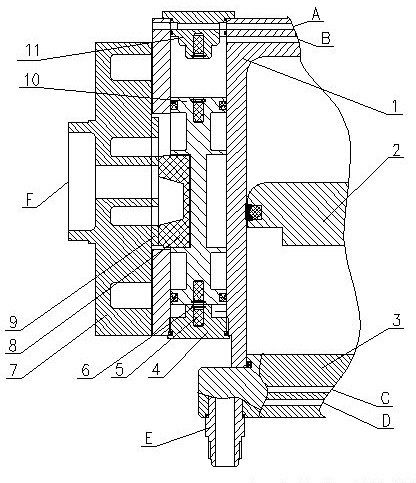
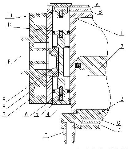
[0014] E is the main intake port of compressed air. Compressed air enters the lower chamber or upper chamber of the cylinder through the air distribution block 7. The upper and lower chambers of the reversing piston 10 enter the compressed air at the same time. The cylinder piston 2 pushes the cylinder piston 2 under the action of compressed air. Movement up or down. When moving to the upper end, the cylinder piston pushes the pilot valve to work, and the compressed air in the upper chamber of the reversing piston 10 passes through the air inlet B of the upper pilot valve and then to the exhaust hole A of the upper pilot valve to communicate with the atmosphere. The 10 lower chambers are always connected with compressed air, and the reversing piston 10 is subjected to two forces simultaneously, compressed air force and magnetic force. When the compressed air is greater than the magnetic force, pushing the reversing piston 10 drives the slider 8 to move upward. With the change ...


PUM


Abstract

The invention relates to a pneumatic two-position four-way reversing valve. A traditional built-in two-position four-way reversing valve of a pneumatic motor can stop at a dead-point position in the operating process, i.e. an air-inlet cavity of an air-distributing chamber is directly communicated with an air-discharging opening through a slide block to cause a spraying machine to stop working, and a dead-point phenomenon is strictly prohibited to appear on the spraying machine on an automatic spraying flow line. In the invention, aiming at the deficiency, on the basis of a traditional two-position four-way valve, permanent magnets are inlaid in a reversing piston, an upper end-cover hole and a lower end-cover hole, and the dead-point difficult problem of the two-position four-way valve appearing in the reversing process is solved through the change of magnet forces and friction forces.

Description

technical field [0001] The invention relates to a reciprocating air motor for a pneumatic airless spraying machine, a gluing machine or other purposes, in particular to a pneumatic two-position four-way reversing valve built into the air motor. Background technique [0002] The existing pneumatic airless spraying machine or pneumatic gluing machine is composed of an air motor and a paint hydraulic pump, and the air motor is the core part of the pneumatic airless spraying machine, which provides reliable power for the pneumatic airless spraying machine . The air motor of the airless spraying machine continuously enters the compressed air from the upper or lower chamber of the cylinder through the air distribution reversing mechanism, and pushes the piston to move up or down, while the compressed air in the lower or upper chamber of the cylinder must be instantaneous Exhaust to atmosphere through the exhaust port. The two-position four-way reversing valve built into the ex...

Claims


Application Information

Patent Timeline
IPC IPC(8): F16K11/065F16K31/122F16K31/08
Inventor 石安涛郭巍
Owner CHONGQING CHANGJIANG COATING EQUIP
Learn More