
Oil seal structure used in high speed motor

A high-speed motor and oil seal technology, applied in electrical components, electromechanical devices, electric components, etc., can solve the problems of reducing the service life of the motor and easy leakage, and achieve the effect of improving the sealing performance, simple structure, and weakening the leakage transmission capacity.

Active Publication Date: 2013-11-13
WUXI GL TUBRO COMPRESSOR
View PDF7 Cites 0 Cited by
  • Summary
  • Abstract
  • Description
  • Claims
  • Application Information

AI Technical Summary

Problems solved by technology

[0002] In the process of developing high-speed motors for high-speed centrifugal fans, after repeated tests, it is feasible to use improved tilting pad bearings to replace magnetic suspension bearings, but because the pressure oil in the tilting pad bearings is easy to leak into the inner cavity of the motor, the reduction The service life of the motor, so a special oil seal structure is required to prevent the leakage of pressure oil

Method used


Image

  • Oil seal structure used in high speed motor

Examples


Embodiment Construction

[0011] Below the present invention will be further described in conjunction with accompanying drawing:

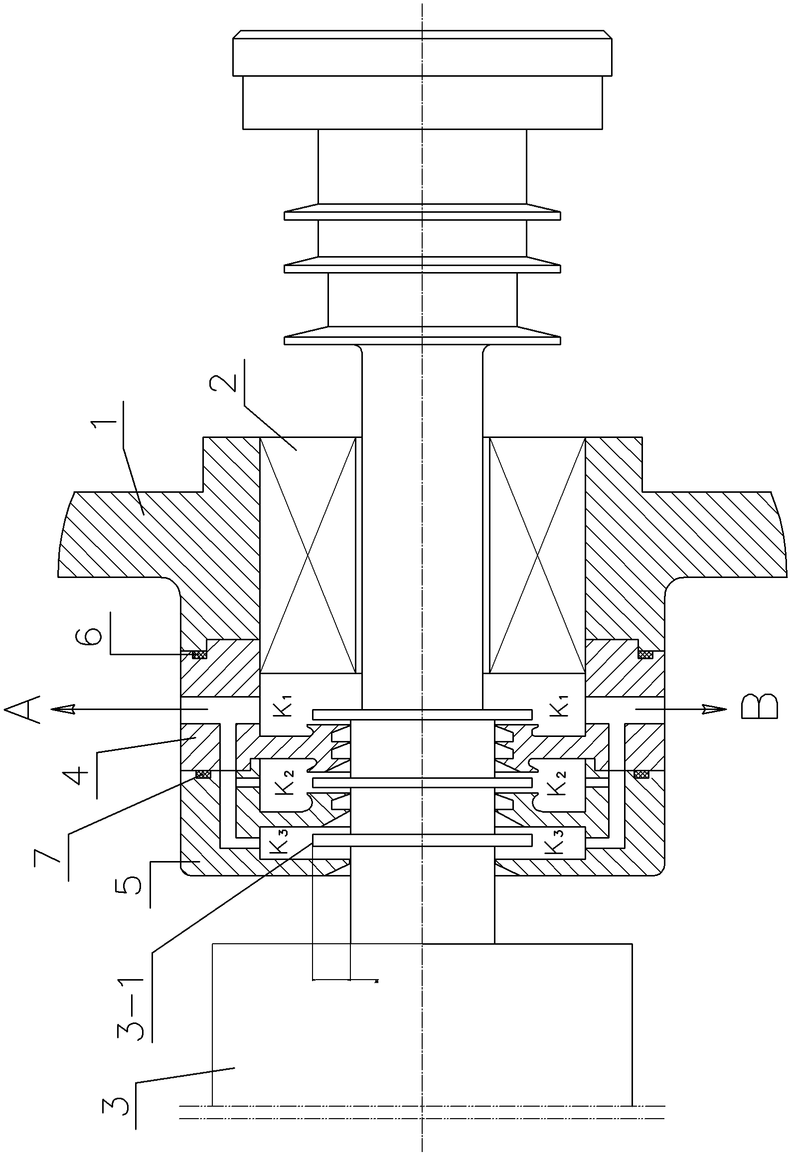
[0012] Such as figure 1 As shown: the present invention includes a casing 1, a bearing 2, a rotor 3, a first oil seal 4, a second oil seal 5, a first O-ring 6, a second O-ring 7, and the like.

[0013] The rotor 3 is installed on the central axis of the bearing hole of the casing 1 by means of the bearing 2, and the first O-ring 6, the first oil seal 4, the first O-ring 6, the first oil seal 4, and the Two O-rings 7, the second oil seal 5; the first oil seal 4 and the second oil seal 5 are provided with several serrations, and the serrations and the rotor 3 form a labyrinth seal structure; the rotor 3 is provided with three The convex ring 3-1 divides the sawtooth into three subsections to form a three-level labyrinth structure and constitutes three first-level inter-space K1, second-level inter-space K2, and third-level inter-space K3; the first inter-level space K1 , Th...


PUM


Abstract

The invention disclosed an oil seal structure used in a high speed motor. The oil seal structure comprises: a shell, a bearing and a rotor. The rotor is installed on a central axis of a shell bearing hole through the bearing. A boss of an inside of the bearing hole of the shell is successively equipped with a first O-shaped circle, a first oil seal component, a second O-shaped circle and a second oil seal component. Several sawtooths are arranged on the first oil seal component and the second oil seal component. The sawtooths and the rotor form a labyrinth seal structure. The rotor is provided with three convex rings. The three convex rings divides the sawtooths into three parts so as to form a three grade labyrinth structure and a first interstage space, a second interstage space and a third interstage space. In the invention, a structure is simple, compact and reasonable. A pressure balance hole which is above the interstage spaces can be used to reduce an adsorption block phenomenon of a lubrication oil so that the lubrication oil can timely return to an oil tank through an oil return hole below. Simultaneously, heights of the convex rings on the rotor are high, which can effectively reduce a leakage transmission ability of the oil between the interstage and tightness of the labyrinth oil seal structure can be increased.

Description

technical field [0001] The invention relates to an oil seal structure for a high-speed motor, in particular to a seal structure for preventing pressure oil in a tilting pad bearing from leaking into the inner cavity of the motor, and belongs to the technical field of mechanical structures. Background technique [0002] In the process of developing high-speed motors for high-speed centrifugal fans, after repeated tests, it is feasible to use improved tilting pad bearings to replace magnetic suspension bearings, but because the pressure oil in the tilting pad bearings is easy to leak into the inner cavity of the motor, the reduction The service life of the motor, so a special oil seal structure is required to prevent the leakage of pressure oil. Contents of the invention [0003] The purpose of the present invention is to prevent pressure oil from leaking into the inner cavity of the motor, thereby providing an oil seal structure for high-speed motors, which is improved fro...

Claims


Application Information

Patent Timeline
Patent Type & Authority Patents(China)
IPC IPC(8): H02K5/16
Inventor 金华明金炳庆
Owner WUXI GL TUBRO COMPRESSOR
Learn More