motor rotor

A rotor and motor technology, applied in the field of rotor structure, can solve problems affecting the overall quality of the motor 8, leakage of lubricating oil, increased vibration and noise, etc.

Active Publication Date: 2016-09-14
SUNONWEALTH ELECTRIC MACHINE IND
View PDF5 Cites 0 Cited by
  • Summary
  • Abstract
  • Description
  • Claims
  • Application Information

AI Technical Summary

Problems solved by technology

Although this other existing structure slightly reduces the axial gap between the elastic buckle 932 and the slot 921 along the mandrel 92, a space must be reserved for the deformation of the elastic buckle 932 based on the slot 921. , and the matching margin of the clip groove 921 and the buckle 93 during manufacture, it is still impossible to completely eliminate the gap between each of the elastic clips 932 and the clip groove 921, so when the rotor 9 rotates, the hub 91 will still be relatively The mandrel 92 produces axial displacement and generates noise, and the fastening part 93 is made of a more rigid material (such as: metal material), so the fastening part 93 is assembled on the mandrel 92 and passed through a long process. After time is used, each elastic buckle 932 is prone to elastic fatigue, resulting in a larger and larger gap between each elastic buckle 932 and the slot 921, and aggravates its vibration noise, affecting the overall quality of the motor 8
[0010] In addition, although the fastening member 93 is an annular body, the inner wall of the through hole 931 is protrudingly formed with each elastic buckle 932, and each adjacent elastic buckle 932 is formed with a split groove 933, Therefore, the elastic clips 932 of the fastening member 93 for snapping into the slot 921 are still discontinuous, so that the lubricating oil of the bearing 84 in the motor 8 is easy to seep and lose through the slots 933, Affect the service life of the motor 8

Method used


Image

  • motor rotor
  • motor rotor
  • motor rotor

Examples


Embodiment Construction

[0039] In order to make the above-mentioned and other objects, features and advantages of the present invention more comprehensible, the preferred embodiments of the present invention are specifically cited below, together with the accompanying drawings, and are described in detail as follows:

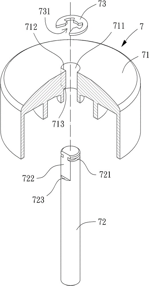
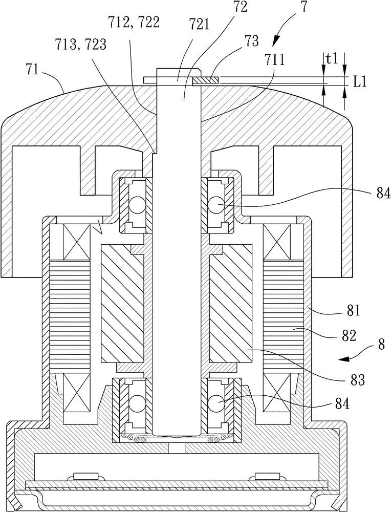
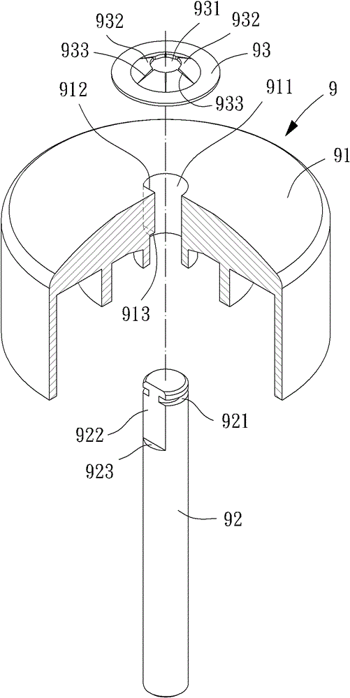
[0040] Please refer to Figure 5 and 6 As shown, the rotor 1 of the motor of the present invention includes a hub 11 , a shaft 12 and a joint 13 . Wherein, the mandrel 12 is assembled and fixed with the hub 11 by using the coupling part 13 .

[0041] The hub 11 has a top surface 111, and the top surface 111 is provided with a perforation 112 through the hub 11, the perforation 112 can be located at the center of the top surface 111, and the inner hole wall of the perforation 112 is further provided with a plane 113 And a first stop surface 114, the plane 113 can be parallel to the axis of the perforation 112, the first stop surface 114 can be perpendicular to the axis of the perforat...


PUM


Abstract

A rotor of a motor includes a hub, a spindle and a joint. The hub is provided with a through hole, the mandrel passes through the through hole, and the outer peripheral surface of the mandrel is provided with a diameter-reducing portion, and the joining piece is a continuous annular body which is elastic and does not have split grooves and gaps, and the joining piece has an inner The annular hole allows the mandrel to pass through, and the coupling part is tightly combined with the diameter-reducing part. Therefore, when the rotor is used in a motor, the axial vibration of the wheel hub relative to the spindle can be reduced and the lubricating oil in the inner bearing of the motor can be prevented from being lost.

Description

technical field [0001] The invention relates to a rotor of a motor, in particular to a rotor structure which can reduce the axial vibration of the hub relative to the spindle and prevent the loss of lubricating oil in the inner bearing of the motor. Background technique [0002] Please refer to figure 1 As shown, the rotor 7 of the conventional motor includes a hub 71 , a spindle 72 and a metal C-shaped retaining ring 73 . The hub 71 is provided with a through hole 711 , and the hole wall of the through hole 711 is further provided with a plane 712 and a first stop surface 713 . An engaging groove 721 , a cutting surface 722 and a second stop surface 723 are formed on the outer peripheral surface of the mandrel 72 . The metal C-shaped buckle 73 is made of metal and has an opening 731 on one side. [0003] Refer again figure 1 and 2 As shown, when the rotor 7 is assembled, the mandrel 72 passes through the through hole 711, the cut surface 722 abuts against the plane 712...

Claims


Application Information

Patent Timeline
Patent Type & Authority Patents(China)
IPC IPC(8): H02K1/22H02K1/28
Inventor 洪银树单多年吴哲豪
Owner SUNONWEALTH ELECTRIC MACHINE IND
Why Eureka
Try Eureka