Hollow glass with sun-shading curtain inside

A sunshade and glass technology, applied in parallel glass structures, shading screens, etc., can solve the problems of unsatisfactory limit effect, large operation force, and inconvenient operation.

Inactive Publication Date: 2012-04-11
广州东玻装饰工程有限公司
View PDF6 Cites 1 Cited by
  • Summary
  • Abstract
  • Description
  • Claims
  • Application Information

AI Technical Summary

Problems solved by technology

The operating device adopts the method of sliding directly on the surface of the glass medium. Due to the large friction force of the sliding method, the operation force is relatively large, and the control accuracy is not easy to grasp, so the operation is very inconvenient
There is an operating device using ordinary rollers on the market, which can roll directly on the contact surface and is easy to operate, but when the power on the operating device along the direction of the contact surface is cancelled, if the gravity of the operating device has a component force along the horizontal direction of the contact surface, Then the friction between the roller and the contact surface alone is not enough to stop the operating device, and an additional limit mechanism needs to be added; even if the operating device is placed horizontally, slight touch and vibration can easily cause it to slide, and the limit effect is not ideal.

Method used


Image

  • Hollow glass with sun-shading curtain inside
  • Hollow glass with sun-shading curtain inside
  • Hollow glass with sun-shading curtain inside

Examples


Embodiment 1

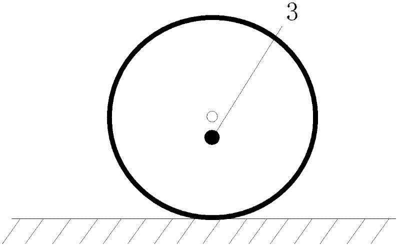
[0027] Embodiment one: if image 3 As shown, the section of the roller along the vertical axis 9 is circular, and the axis 9 deviates from the center of the circle. The resistance position refers to the position closest to the axis 9 on the wheel surface. There is only one position, and the flexible material 302 surrounds the entire wheel surface . The roller only needs to ensure that the axis 9 deviates from the axis 9, and the processing is simple and the cost is low.

Embodiment 2

[0028] Embodiment two: if Figure 4 As shown, the cross-section of the roller along the vertical direction of the axis 9 is elliptical, and the resistance position refers to the position closest to the axis 9 on the wheel surface. Due to the symmetrical characteristics of the ellipse, there are two positions, and the flexible material 302 surrounds the entire Wheel surface. The roller utilizes the natural properties of the ellipse to realize two resistance positions with high control precision.

Embodiment 3

[0029]Embodiment three: as Figure 5 As shown, the cross-section of the roller along the vertical direction of the axis 9 is a polygon, and the resistance position refers to each plane of the roller. The flexible material 302 can surround the entire wheel surface to enhance the friction of the entire wheel surface; it can also be distributed on each surface of the roller. Flat sides for enhanced friction at resistance locations. The number of resistance positions of the roller is the same as the number of sides of the polygon, so multiple resistance positions can be realized, and the control accuracy is higher. In addition, the resistance position is a plane, and the friction force with the contact surface is large, so the limit effect is better.


PUM


Abstract

The invention discloses hollow glass with a sun-shading curtain inside. The hollow glass comprises glass media on two faces, the sun-shading curtain arranged between the glass media on the two faces, a traction mechanism for controlling the sun-shading curtain, and a traction device fixed on the traction mechanism, wherein an operating device is arranged at a position, opposite to the traction device, outside the hollow glass; at least one of the operating device and the traction device comprises a magnetic material, so the operating device is connected with the traction device through a magnetic force; and at least one of the operating device and the traction device comprises a roller of which the roller surface is embedded with a flexible material. In the hollow glass, as the roller with a limiting structure is selected, the sun-shading curtain can be limited automatically based on a theory that the magnetic force is large in a near place and small in a far place under the condition of proper magnetic field intensity; therefore, the operating difficulty is reduced and the operating feel is improved.

Description

technical field [0001] The invention relates to a hollow glass with a sunshade inside. Background technique [0002] At present, the field of building energy saving is gradually being paid attention to. As an important part of building energy saving, insulating glass is loved by consumers because of its good heat insulation and sound insulation effects. At present, there is a popular hollow glass with sunshade installed inside. The sunshade can be controlled by magnetic traction to adjust the light intensity in the room. The specific method is: install the sunshade inside the hollow glass and install it on the traction mechanism Fix a magnetic traction device, and then set an operating device outside the insulating glass, which is magnetically connected with the traction device. By controlling the operation device, the traction device can be driven to move, thereby realizing the control of the sunshade. The operating device adopts the method of sliding directly on the surfa...

Claims


Application Information

Patent Timeline
Patent Type & Authority Applications(China)
IPC IPC(8): E06B3/66E06B9/24
Inventor 邢皓宇
Owner 广州东玻装饰工程有限公司
Why Eureka
Try Eureka