Reducing and sudden expansion type inner energy dissipator

A technology of energy dissipation and sudden expansion, which is applied in water conservancy projects, sea area projects, coastline protection, etc., can solve the problems of increased project cost, large amount of construction work, small operating flow, etc., and achieves easy design and construction, anti-cavitation performance Good, the effect of improving the energy dissipation rate

Inactive Publication Date: 2012-04-11
SICHUAN UNIV
View PDF4 Cites 3 Cited by
  • Summary
  • Abstract
  • Description
  • Claims
  • Application Information

AI Technical Summary

Problems solved by technology

[0002] In 1967, Samuel O.Russell etc. disclosed a method of utilizing the sudden shrinkage and expansion of water flow to cause head loss to dissipate energy (see Samuel O.Russell, James W.Ball.Sudden-enlargement energy dissipator for Mica dam.Journal of the hydraulics division ASCE, 7(1967): 41~56), the structure of the energy dissipator of this structure is complicated, and the construction volume is large. It is only suitable for projects with low operating water head and small operating flow. When the water head exceeds 100m, the energy dissipation The tool itself is prone to cavitation damage
[0003] Chinese patent ZL200610021207.2 discloses a hole plug energy dissipator. Although the hole plug energy dissipator solves the problem of energy dissipation in the flood discharge tunnel under high water head, its inlet section is prone to cavitation under high water head.
In order to adapt to the working conditions of high water head, it is necessary to expand the inlet and outlet areas during application, that is, to increase the area shrinkage ratio, which reduces the energy dissipation rate of single-stage hole plugs, so it is necessary to set up multi-stage hole plugs. In the embodiment, it is 3 levels) to meet the energy dissipation requirements of the project, and the increase in the number of levels of hole plug energy dissipation will inevitably increase the project cost and prolong the construction period

Method used


Image

  • Reducing and sudden expansion type inner energy dissipator
  • Reducing and sudden expansion type inner energy dissipator
  • Reducing and sudden expansion type inner energy dissipator

Examples


Embodiment 1

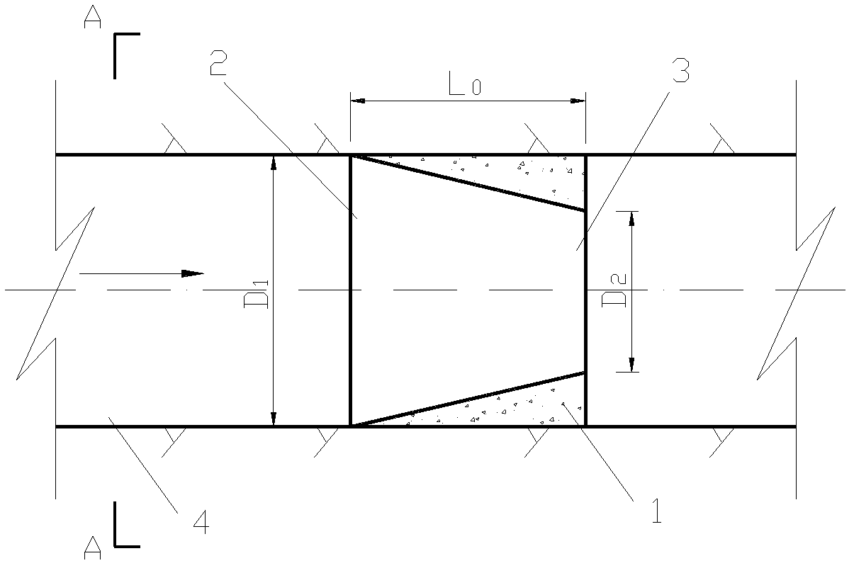
[0024] In this embodiment, the structure of the tapered and suddenly expanded internal flow energy dissipator is as follows figure 2 , image 3 As shown, it consists of a base body 1 and flow holes provided in the base body, the flow hole is a constricted truncated conical hole with the inlet 2 larger than the outlet 3 .

[0025] The tapered and suddenly expanded internal flow energy dissipation device described in this embodiment is used for the hole diameter D 1 = 20m spillway tunnel energy dissipation, the relevant dimensions are as follows: flow hole inlet diameter = spillway tunnel diameter D 1 =20m, outlet diameter of flow hole D 2 =0.415D 1 =8.3m, the length of the flow hole is the same as the length of the base, both are L 0 , the L 0 =0.5D 1 = 10m. The tapered-sudden-expanded internal flow energy dissipator described in this embodiment is made of conventional concrete.

Embodiment 2

[0027] In this embodiment, the structure of the tapered and suddenly expanded internal flow energy dissipator is as follows figure 2 , image 3 As shown, it consists of a base body 1 and flow holes provided in the base body, the flow hole is a constricted truncated conical hole with the inlet 2 larger than the outlet 3 .

[0028] The tapered and suddenly expanded internal flow energy dissipation device described in this embodiment is used for the hole diameter D 1 = 20m spillway tunnel energy dissipation, the relevant dimensions are as follows: flow hole inlet diameter = spillway tunnel diameter D 1 =20m, outlet diameter of flow hole D 2 =0.4D 1 =8.0m, the length of the flow hole is the same as the length of the base, both are L 0 , the L 0 =0.5D 1 = 10m. The tapered-sudden-expanded internal flow energy dissipator described in this embodiment is made of conventional concrete.

Embodiment 3

[0030] This embodiment is a flood discharge tunnel converted from a diversion tunnel of a large power station, and the diameter of the flood discharge tunnel is D 1 20m, maximum water head 200m, discharge flow 2600m 3 / s, a first-level tapered and suddenly expanded internal flow energy dissipator is arranged, such as Figure 5 shown.

[0031] The tapered and suddenly expanded internal flow energy dissipator 5 used in this embodiment is the tapered and suddenly expanded internal flow energy dissipator with the structure and size described in Embodiment 1. After the water flows through the energy dissipator, the head of the piezometric tube is reduced by 79m, that is, the energy dissipating head is 79m. In this embodiment, the energy dissipation requirements of the project can be met only by using one-stage tapered and suddenly expanded internal flow energy dissipator, and the inlet section of the energy dissipator has no cavitation.


PUM


Abstract

The invention provides a reducing and sudden expansion type inner energy dissipater. The energy dissipater consists of a matrix and an overflow hole arranged in the matrix, wherein, the overflow hole is in a contractible cone frustum shape, the inlet of the overflow hole is bigger than the outlet of the overflow hole, the diameter of the inlet of the overflow hole is equal to the diameter D1 of a flood discharge hole, the diameter D2 of the outlet of the overflow hole is equal to 0.1D1-0.7D1, and the overflow hole and the matrix have the equal length of L0 which is equal to 0.4D1-2.5D1. The reducing and sudden expansion type inner energy dissipater can be applied to energy dissipation in the pressured flood discharge hole; when in use, at least one reducing and sudden expansion type inner energy dissipater is arranged in the pressured flood discharge hole; and in the case of at least two reducing and sudden expansion type inner energy dissipaters, the distance between two neighboring energy dissipaters is at least 2D1, wherein, D1 is the diameter of the flood discharge hole.

Description

technical field [0001] The invention belongs to energy dissipation facilities used in water conservancy and hydropower projects, in particular to an energy dissipation facility used for energy dissipation in pressurized flood discharge tunnels. Background technique [0002] In 1967, Samuel O.Russell etc. disclosed a method of utilizing the sudden shrinkage and expansion of water flow to cause head loss to dissipate energy (see Samuel O.Russell, James W.Ball.Sudden-enlargement energy dissipator for Mica dam.Journal of the hydraulics division ASCE, 7(1967): 41~56), the structure of the energy dissipator of this structure is complicated, and the construction volume is large. It is only suitable for projects with low operating water head and small operating flow. When the water head exceeds 100m, the energy dissipation The tool itself is prone to cavitation damage. [0003] Chinese patent ZL200610021207.2 discloses a hole plug energy dissipator. Although the hole plug energy di...

Claims


Application Information

Patent Timeline
Patent Type & Authority Applications(China)
IPC IPC(8): E02B8/06
Inventor 许唯临田忠王韦刘善均张建民曲景学邓军张法星李乃稳
Owner SICHUAN UNIV
Why Eureka
Try Eureka