
Taking-out device of long monocrystalline silicon rods

A technology for taking out a device and a single crystal silicon rod, which is applied in the directions of single crystal growth, crystal growth, chemical instruments and methods, etc., can solve the problem that the secondary chamber 104 and the furnace cover 102 cannot be rotated reliably synchronously, the work intensity is increased, and the time and effort is consuming. problems, to achieve the effect of improving safety, improving safety, and accurate centering

Active Publication Date: 2012-04-11
北京京仪仪器仪表研究总院有限公司
View PDF3 Cites 2 Cited by
  • Summary
  • Abstract
  • Description
  • Claims
  • Application Information

AI Technical Summary

Problems solved by technology

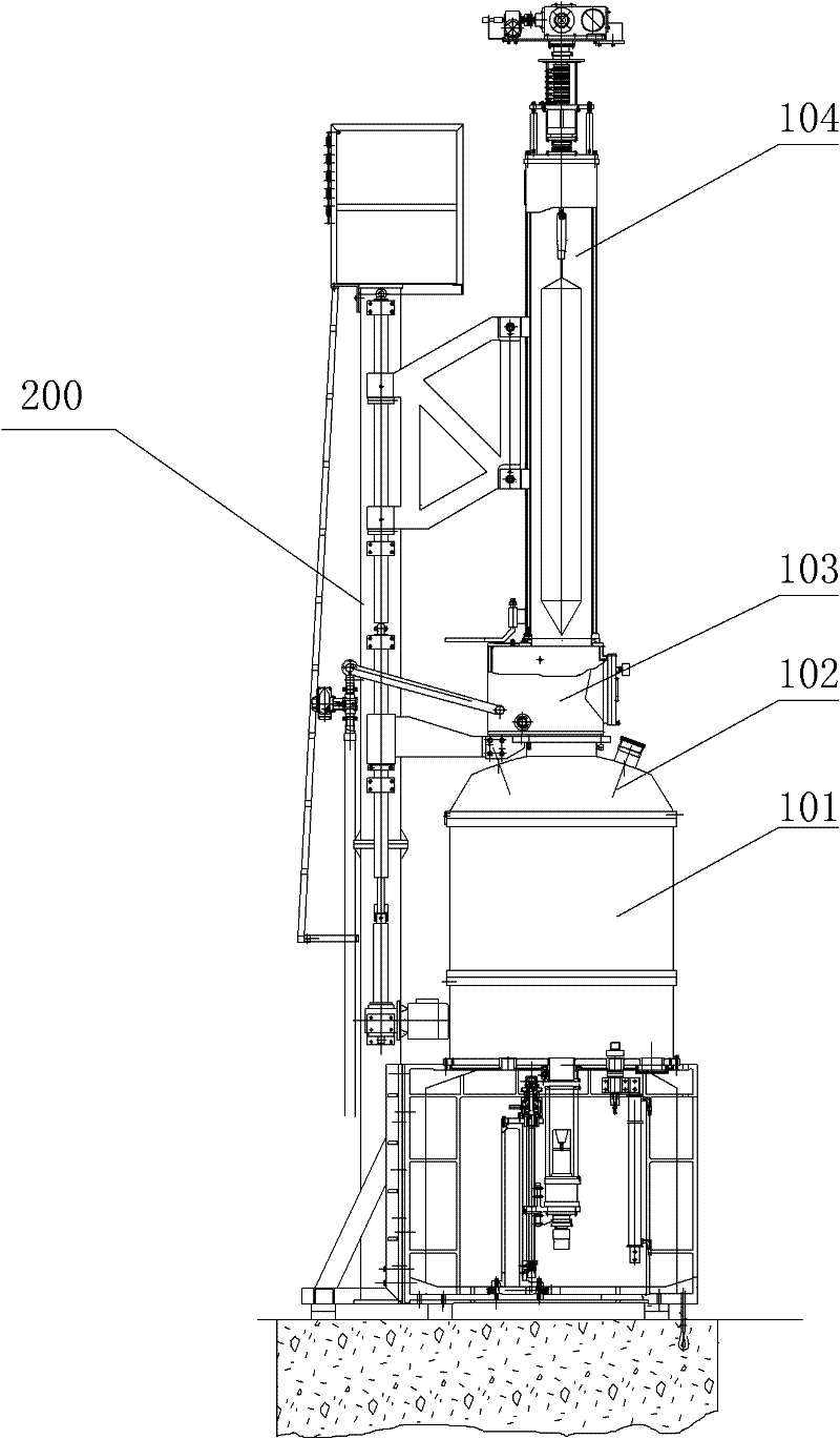
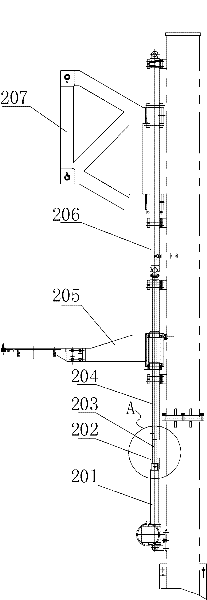
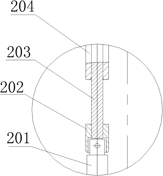
Although the prior art adopts the structure of adding a vertical plate 208 on the flap valve 103, to a certain extent, the synchronous rotation of the auxiliary chamber 104 and the furnace cover 102 can be realized and the safety of operation can be improved, but the auxiliary chamber 104 and the furnace cover cannot be realized. The reliable synchronous rotation of 102 is easy to cause shaking between the auxiliary chamber 104, the flap valve 103, and the furnace cover 102, and each operation needs to install or remove the vertical plate 208 according to the length of the monocrystalline silicon rod to be produced, which is time-consuming and labor-intensive. At the same time, in order to ensure the accurate cooperation between the auxiliary chamber and the flap valve when the furnace is combined, the vertical plate 208 needs to be removed every time. The installation and removal of the vertical plate 208 has a certain height, which is inconvenient to operate

Method used


Image

  • Taking-out device of long monocrystalline silicon rods
  • Taking-out device of long monocrystalline silicon rods
  • Taking-out device of long monocrystalline silicon rods

Examples


Embodiment Construction

[0049] In order to have a clearer understanding of the technical features, purposes and effects of the present invention, the specific implementation manners of the present invention will now be described with reference to the accompanying drawings.

[0050] Please refer to Figure 5 , Figure 6 , which is a structural schematic diagram of Embodiment 1 of the device for taking out long monocrystalline silicon rods of the present invention and Figure 5 Schematic diagram of the enlarged structure in part B. As shown in the figure, the device for taking out long single crystal silicon rods proposed by the present invention is used in silicon single crystal furnaces, including electric push rods 1, electric push rod connecting blocks 2, jacking shafts 3, furnace Lid lifting shaft 4, furnace lid lifting connecting piece 5, auxiliary chamber lifting shaft 6 and auxiliary chamber lifting connecting piece 7, jacking shaft 3 runs through furnace lid lifting shaft 4 and the two ends ...


PUM


Abstract

The invention discloses a taking-out device of long monocrystalline silicon rods. The taking-out device is used for a silicon single crystal furnace, and comprises an electric pushing rod, an electric pushing rod connection block, a jacking shaft, a furnace cover lifting shaft, a furnace cover lifting connection piece, an auxiliary chamber lifting shaft and an auxiliary chamber lifting connection piece which are sequentially arranged from bottom to top, wherein the jacking shaft penetrates through the furnace cover lifting shaft, two ends of the jacking shaft respectively extend out of the end parts of the furnace cover lifting shaft, the jacking shaft can move upwards and downwards in the furnace cover lifting shaft, the upper end of the jacking shaft is connected with the lower end of the auxiliary chamber lifting shaft, the lower end of the jacking shaft is connected with the electric pushing rod connection block, and a detachable stopping component is arranged on the jacking shaft between the bottom of the furnace cover lifting shaft and the electric pushing rod connection block. The taking-out device can take out the long monocrystalline silicon rods in a stable, safe, convenient and reliable mode, and simultaneously can be rapidly and conveniently switched to meet taking-out requirements of monocrystalline silicon rods with different lengths.

Description

technical field [0001] The invention relates to the field of production of long single crystal silicon rods in the semiconductor industry, in particular to a device for taking out long single crystal silicon rods. Background technique [0002] With the use of secondary feeding equipment and processes for silicon single crystal furnaces, the length of silicon single crystal rods that can be produced by silicon single crystal furnaces has been significantly increased. At the same time, the large-size monocrystalline silicon ingot production furnace can produce longer monocrystalline silicon ingots at one time because of its large feed capacity. For example, the single crystal silicon rod production furnace with a diameter of 8 inches can feed 120Kg at a time, and the length of the single crystal silicon rod can be significantly increased when the same feed amount is used to produce a single crystal silicon rod with a diameter of 6 inches. In order to adapt to the production r...

Claims


Application Information

Patent Timeline
IPC IPC(8): C30B15/30
Inventor 冯冬芳李进
Owner 北京京仪仪器仪表研究总院有限公司
Learn More