
Construction instrument maintenance tool box

A technology for repairing tools and instruments, which is applied in the direction of manufacturing tools and tool storage devices, etc. It can solve problems such as shaking inside the box, inconvenient removal of tools, damage to maintenance tools, etc., to achieve convenient removal process, good effect, and stable effect

Inactive Publication Date: 2021-02-02
江苏弘汉生物科技有限公司
View PDF0 Cites 0 Cited by
  • Summary
  • Abstract
  • Description
  • Claims
  • Application Information

AI Technical Summary

Problems solved by technology

[0002] There are many types of construction equipment, which are usually used for construction operations in the construction process. Construction equipment will break down during use, and relevant maintenance tools are required for maintenance of construction equipment. Therefore, toolboxes are usually carried during construction to keep the The maintenance tools are placed inside the tool box. The existing construction equipment maintenance tool boxes are not stable enough when the tools are placed inside, and the inside of the box shakes, causing damage to the maintenance tools. Secondly, some tool boxes use magnetic suction. to ensure the stability of the tool, but the adsorption of the magnet makes it inconvenient to take out the tool. Therefore, we propose a construction equipment maintenance tool box

Method used


Image

  • Construction instrument maintenance tool box
  • Construction instrument maintenance tool box
  • Construction instrument maintenance tool box

Examples


Embodiment Construction

[0017] In order to make the technical means, creative features, goals and effects achieved by the present invention easy to understand, the present invention will be further described below in conjunction with specific embodiments.

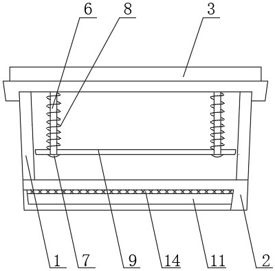
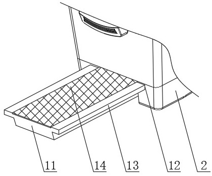
[0018] Such as Figure 1-4 As shown, a construction equipment maintenance toolbox includes a box body 1, a bottom plate 2 is provided at the lower end of the box body 1, a box cover 3 is provided at the upper end of the box body 1, and a limit rod 6 is provided on the outer surface of the lower end of the box cover 3, The lower end of the limit rod 6 is provided with a limit head 7, and the outside of the limit rod 6 is provided with a compression spring 8, and the outside of the limit rod 6 is provided with a limit pressure plate 9 near the lower end of the compression spring 8, and the outer surface of the lower end of the base plate 2 is provided with Hiding into the groove 10, the inside of the hiding groove 10 is provided with a movable plate...


PUM


Abstract

The invention discloses a construction instrument maintenance tool box. The box comprises a box body, wherein a bottom plate is arranged at the lower end of the box body, a box cover is arranged at the upper end of the box body, a limiting rod is arranged on the outer surface of the lower end of the box cover, a limiting head is arranged at the lower end of the limiting rod, a compression spring is arranged on the outer side of the limiting rod, a limiting pressing plate is arranged on the outer side, close to the lower end of the compression spring, of the limiting rod, a hiding groove is formed in the outer surface of the lower end of the bottom plate, a movable plate is arranged on the inner side of the hiding groove, limiting protruding blocks are arranged on the outer surfaces of thefront end and the rear end of the movable plate, and sliding rails are arranged at the positions, corresponding to the limiting protruding blocks, of the inner wall of the hiding groove, and a magnetblock is arranged on the outer surface of the upper end of the movable plate. According to the construction instrument maintenance tool box, tools on the inner side can be stably placed, the tools canbe prevented from being affected by magnetic attraction in a taking-out process, and convenience is achieved.

Description

technical field [0001] The invention relates to the field of tool boxes, in particular to a construction appliance maintenance tool box. Background technique [0002] There are many kinds of construction equipment, which are usually used for construction operations in the construction process. Construction equipment will break down during use, and related maintenance tools are required for maintenance of construction equipment. Therefore, toolboxes are usually carried during construction to keep the The maintenance tools are placed inside the tool box. The existing construction equipment maintenance tool boxes are not stable enough when the tools are placed inside, and the inner side of the box shakes, causing damage to the maintenance tools. Secondly, some tool boxes use magnetic suction. To ensure the stability of the tool, but the adsorption effect of the magnet makes it inconvenient to take out the tool. Therefore, we propose a construction equipment maintenance tool box...

Claims


Application Information

Patent Timeline
IPC IPC(8): B25H3/02
CPCB25H3/02
Inventor 不公告发明人
Owner 江苏弘汉生物科技有限公司
Learn More