Structure on end part of linkage curved bar

A technology of end structure and curved rod, which is applied in the direction of steering mechanism, bicycle accessories, transportation and packaging, etc., can solve the problems of many accessories, complex structure, linkage operation error, etc., and achieve simple overall structure, stable working state and small torque Effect

Inactive Publication Date: 2012-04-11
SHANGHAI YONGLONG INDAL & TRADING
View PDF1 Cites 0 Cited by
  • Summary
  • Abstract
  • Description
  • Claims
  • Application Information

AI Technical Summary

Problems solved by technology

[0003] It is not difficult to see from the above comparative documents that the structure of the existing child carriage rear control steering device is relatively complicated, and there are many accessories, and linkage operation errors are prone to occur in actual use.

Method used


Image

  • Structure on end part of linkage curved bar
  • Structure on end part of linkage curved bar

Examples


Embodiment Construction

[0009] The present invention will be further described below with reference to the accompanying drawings.

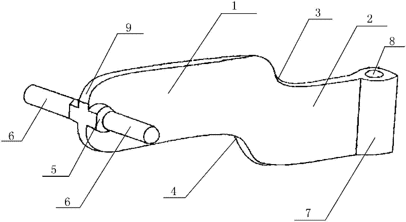
[0010] The present invention is a linkage curved rod end structure, which mainly includes an upper linkage piece 1 and a lower linkage piece 2, which is different from the prior art in that the upper edge of the upper linkage piece 1 is parallel and higher than the lower linkage piece 2 The upper edge of the upper linkage piece 1 is parallel to and higher than the lower edge of the lower linkage piece 2. The connection between the upper edge of the upper linkage piece 1 and the lower linkage piece 2 forms an upper arc surface 3. The upper linkage piece 1 and the lower linkage piece The lower arc surface 4 is formed at the joint of the lower edge of the linkage piece 2, and an assembly platform 5 is provided on both sides of the end of the upper linkage piece 1, and a linkage column 6 is provided on the surface of the assembly platform 5.

[0011] In specific implementati...


PUM


Abstract

The invention discloses a structure on the end part of a linkage curved bar. The structure is characterized in that: an upper edge of an upper linkage sheet is parallel to and higher than an upper edge of a lower linkage sheet; a lower edge of the upper linkage sheet is parallel to and higher than a lower edge of the lower linkage sheet; an upper arc surface is formed at the connection position of the upper edges of the upper linkage sheet and the lower linkage sheet; a lower arc surface is formed at the connection position of the lower edges of the upper linkage sheet and the lower linkage sheet; both sides of the end part of the upper linkage sheet are provided with an assembly platform; and linkage posts are arranged on the surfaces of the assembly platforms. The integral structure of a product is simple; and the structure can be subjected to rear deflection linkage control only by matching a curved linkage bar, is connected with the linkage curved bar by a sleeve and difficultly separated from the linkage curved bar, has a stable working condition, is convenient to operate smoothly, requires low torsion force during deflection, can be operated by a single hand, has extremely high practicability, and has outstanding substantial characteristics and remarkable progress compared with the prior art.

Description

technical field [0001] The invention relates to the technical field of baby carriage accessories, in particular to an end structure of a linkage curved rod, and in particular to its mechanical connection structure. Background technique [0002] Reference document, patent number: ZL200720059625.0, application date: 2007.11.16, publication (announcement) number: CN201169347, this case discloses a "positioning and steering device for baby carriages", including the body, steering wheel, wheels, guide columns, and the bottom of the steering wheel There is a bar-shaped block, and the upper end of the guide column is provided with a card slot that matches the block. There are fixed shafts formed on both sides near the lower end. The shaft is rotationally connected to the wheel. [0003] It is not difficult to see from the above comparative documents that the structure of the existing child carriage rear control steering device is relatively complicated, and there are many accessor...

Claims


Application Information

Patent Timeline
Patent Type & Authority Applications(China)
IPC IPC(8): B62K21/00
Inventor 张才宽
Owner SHANGHAI YONGLONG INDAL & TRADING
Why Eureka
Try Eureka