
Energy generating installation, especially wind power installation

A kind of wind power generation equipment, energy generation technology, applied in the direction of wind power generator components, wind power generation, wind power engine, etc., can solve the problems of long time length, inappropriateness, etc.

Inactive Publication Date: 2012-04-04
格拉尔德黑亨贝格尔
View PDF6 Cites 0 Cited by
  • Summary
  • Abstract
  • Description
  • Claims
  • Application Information

AI Technical Summary

Problems solved by technology

[0007] Although this technical solution allows the direct connection of medium-voltage synchronous generators to the network, the disadvantage of the known implementation is the regulation of the reactive current of the synchronous generators used and thus the voltage regulation of the network due to the use of synchronous generator exciters The relatively long length of time for regulation is not suitable for the requirements of modern power stations

Method used


Image

  • Energy generating installation, especially wind power installation
  • Energy generating installation, especially wind power installation
  • Energy generating installation, especially wind power installation

Examples


Embodiment Construction

[0028] The power of the rotor of the wind power plant is calculated according to the following formula:

[0029] Rotor power = rotor area × power coefficient × wind speed 3 ×air density / 2

[0030] Among them, the power coefficient depends on the high-speed coefficient of the wind power generation equipment (=the ratio of the tip speed of the blade to the wind speed). The rotor of a wind power plant is designed for an optimum power coefficient on the basis of a high-speed coefficient determined during the development process (mostly values ​​between 7 and 9). For this reason, correspondingly low rotational speeds can be set when the wind power plant is operated in the partial load range in order to ensure optimum aerodynamic efficiency.

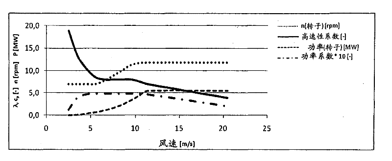
[0031] figure 1 The relationship of rotor power, rotor speed, high speed coefficient and power coefficient is shown for the predetermined speed range of rotor or optimum high speed coefficient of 8.0 to 8.5. It can be seen from the figure ...


PUM


Abstract

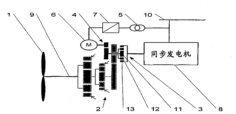
The invention relates to an energy generating installation, especially a wind power station, comprising a drive shaft connected to a rotor (1), a generator (8) and a differential transmission (11 to 13) provided with three drives or outputs. A first drive is connected to the drive shaft, an output is connected to a generator (8), and a second drive is connected to an electrical differential drive (6, 14). The differential drive (6, 14) is connected to a network (10) by means of a frequency converter (7, 15), the blind current of the frequency converter (7, 15) being regulatable.

Description

technical field [0001] The invention relates to an energy generating plant, in particular a wind power plant, with a drive shaft connected to a mover, a generator and a differential gear with three drive or output devices, wherein the first drive device is connected to the drive shaft , the driven device is connected to the generator, the second drive device is connected to the electric differential drive device, and the differential drive device is connected to the network via the frequency converter. [0002] The invention also relates to a method of operation of such an energy generating device. Background technique [0003] Wind power plants are becoming more and more important as power generation facilities. The percentage contribution of electricity generated by wind power is therefore continuously increasing. This in turn leads to new standards for current quality (especially with regard to reactive current regulation and the behavior of wind power plants in the eve...

Claims


Application Information

Patent Timeline
Patent Type & Authority Applications(China)
IPC IPC(8): H02J3/18F03D9/00
CPCY02E10/763H02J3/1885Y02E10/722Y02E40/32Y02E10/72F03D9/003F03D11/02F03D15/00F03D9/255Y02E10/76Y02E40/30F03D9/00H02J3/18F03D15/20
Inventor 格拉尔德·黑亨贝格尔
Owner 格拉尔德黑亨贝格尔
Learn More