
Large-wide-angle low-standing-wave microstrip frequency sweep antenna based on suspended strip slow-wave line

A slow-wave line and strip line technology is applied in the field of phased array antennas, which can solve the problems of difficulty in making high-performance frequency sweep antennas, large standing waves and large losses, and achieve the effects of simple structure, improved performance, and widened application range.

Inactive Publication Date: 2012-03-28
SHAANXI HUANGHE GROUP
View PDF4 Cites 18 Cited by
  • Summary
  • Abstract
  • Description
  • Claims
  • Application Information

AI Technical Summary

Problems solved by technology

This form of feed network is small in size and light in weight, but it has the disadvantages of standing waves and large losses, making it difficult to make high-performance frequency-swept antennas

Method used


Image

  • Large-wide-angle low-standing-wave microstrip frequency sweep antenna based on suspended strip slow-wave line
  • Large-wide-angle low-standing-wave microstrip frequency sweep antenna based on suspended strip slow-wave line
  • Large-wide-angle low-standing-wave microstrip frequency sweep antenna based on suspended strip slow-wave line

Examples


Embodiment Construction

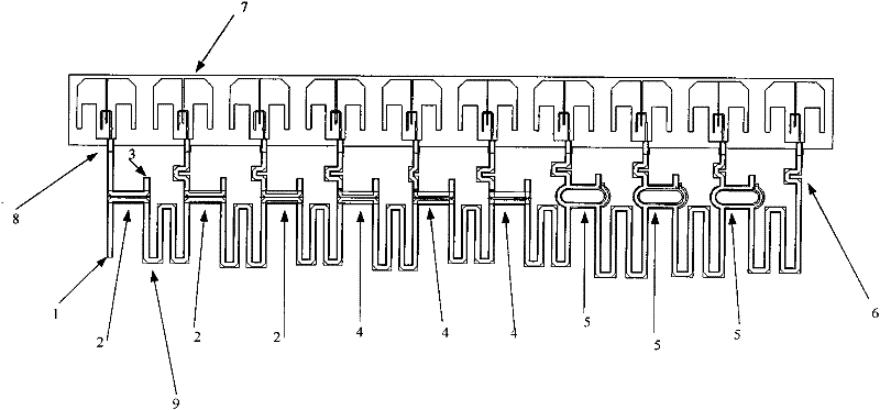
[0026] The invention belongs to the technical field of phased array antennas in the field of radio, and proposes a frequency-swept antenna with a suspended strip line as a slow wave line and an ultra-wideband microstrip antenna as a radiation unit, and uses a suspended strip line coupler to transfer energy Coupled to the radiation unit, the size of the frequency-swept antenna is greatly reduced, the standing wave in the normal direction is reduced, and the wide-angle scanning of the frequency-swept antenna is realized.

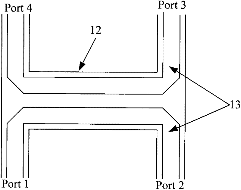
[0027] The technical solution adopted by the present invention to solve the technical problem is: including the narrow side directional coupler 2 of the suspended strip line TEM line, the broad side directional coupler 4 of the suspended strip line TEM line, the coupling of the wide frequency band annular branch line of the suspended strip line Device 5, suspended strip line meander line 9, compensation line 6, ultra-wideband small-sized microstrip dipole anten...


PUM


Abstract

The invention discloses a large-wide-angle low-standing-wave microstrip frequency sweep antenna based on a suspended strip slow-wave line. One end of a suspended strip meander line is used for feeding; the middle of the suspended strip meander line is connected with a plurality of narrow-edge directional couplers, wide-edge directional couplers and broadband circular branch line couplers; the coupling port of each coupler is connected with a section of compensation line; a separating port is connected with a matched load; each compensation line is also connected to an ultra-wideband small-size microstrip dipole antenna; and the tail end of the suspended strip meander line is directly fed into one ultra-wideband small-size microstrip dipole antenna through one section of compensated line. According to the invention, the standing wave is increased; the performance of the frequency sweep antenna is enhanced; the scanning airspace of the frequency sweep antenna is greatly widened; and the structure is simple.

Description

technical field [0001] The invention belongs to the technical field of phased array antennas in the field of radio, and relates to a frequency-sweeping antenna. Background technique [0002] The frequency scanning antenna is an antenna that uses frequency changes to control the beam pointing. It has fast scanning speed and low cost, and is widely used in radar, communication, television and other fields. As early as 1950, frequency-scanning antennas had been applied to the military field, and countries such as the United Kingdom and the United States had equipped a large number of three-coordinate radars using frequency-sweeping antennas. In the civilian field, frequency-swept antennas are widely used due to their low cost. There are a large number of radars that use frequency-swept antennas to detect and monitor ground targets. [0003] Traditional frequency-swept antennas use waveguide serpentine lines or helical lines as slow wave lines, and the radiation unit generally ...

Claims


Application Information

Patent Timeline
Patent Type & Authority Applications(China)
IPC IPC(8): H01Q23/00H01Q1/38
Inventor 崔卫东钟华王一兵尤国军
Owner SHAANXI HUANGHE GROUP
Learn More