
Controlling device capable of automatically cutting off train pipe and exhausting in case of undervoltage main blast line and control method

An automatic cut-off and control device technology, which is applied in the direction of pneumatic brakes, railway car body parts, hydraulic brakes, etc., can solve problems such as failure to implement braking protection measures in time, locomotive safety hazards, etc.

Active Publication Date: 2012-03-28
ZHUZHOU ELECTRIC LOCOMOTIVE CO
View PDF4 Cites 15 Cited by
  • Summary
  • Abstract
  • Description
  • Claims
  • Application Information

AI Technical Summary

Problems solved by technology

However, in practical application, there are the following deficiencies: 1. Existing locomotive main air duct road low pressure protection is not provided with a train pipe exhaust control device, and only implements corresponding braking protection measures through the locomotive circuit logic control unit; 2. When the pressure of the main air duct of the locomotive is too low, in the case of failure or failure of the electrical components of the logic control unit of the locomotive circuit, the braking system of the locomotive cannot implement corresponding braking protection measures in time, which brings great safety to the normal operation of the locomotive Hidden dangers; 3. When the locomotive is operating in the double-connection mode, the double-connection locomotive does not isolate the train pipe on the gas circuit

Method used


Image

  • Controlling device capable of automatically cutting off train pipe and exhausting in case of undervoltage main blast line and control method
  • Controlling device capable of automatically cutting off train pipe and exhausting in case of undervoltage main blast line and control method

Examples


Embodiment Construction

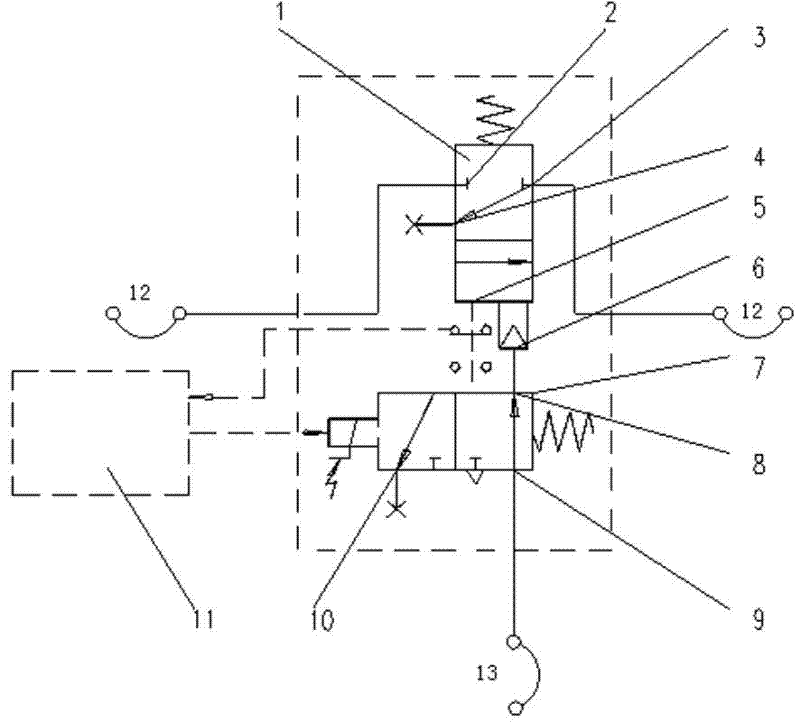
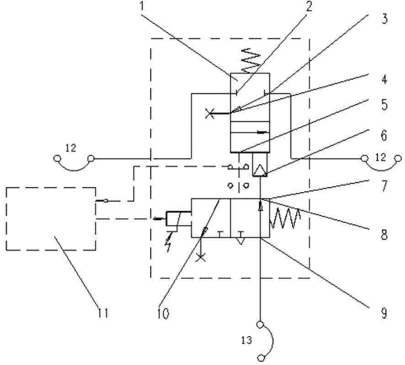
[0014] Such as figure 1 As shown, a control device for automatically cutting off and exhausting the train pipe under pressure in the main air pipeline, including a pneumatic valve 1, the bottom of the pneumatic valve 1 is provided with a micro switch 5 for monitoring the state of the pneumatic valve, and the two sides of the pneumatic valve 1 are provided with Valve ports 2 and 3, valve port 2 is connected to the outlet of the train pipe 12 of the locomotive balance air cylinder relay valve, and valve port 3 is connected to the inlet of the train pipe 12 of the locomotive distribution valve; one side of the pneumatic valve 1 is also provided with an air exhaust port 4, It communicates with the atmosphere.

[0015] The bottom of the pneumatic valve 1 is provided with an enabling valve port 6, and the pneumatic valve 1 is provided with a solenoid valve 7 for controlling the total air pressure of the locomotive. The air outlet 8 at the top of the solenoid valve 7 is connected wit...


PUM


Abstract

The invention discloses a controlling device capable of automatically cutting off a train pipe and exhausting in case of an undervoltage main blast line and a control method. The controlling device comprises a pneumatic valve, wherein the left and right sides of the pneumatic valve are provided with valve ports, the valve port at the left side of the pneumatic valve is connected with a train pipeoutlet of a locomotive equalizing reservoir relay valve, the valve port at the right side of the pneumatic valve is connected with a train pipe inlet of a locomotive distributing valve, an exhaust outlet is arranged at one side of the pneumatic valve, the bottom of the pneumatic valve is provided with an actuating valve port, a magnetic valve is arranged below the pneumatic valve, an air inlet and an air outlet are arranged on the magnetic valve, the air inlet at the top of the magnetic valve is connected with a locomotive main blast line, the air outlet is connected with the actuating valve port, and an exhaust port is also arranged on the magnetic valve. The connection, isolation and automatic exhaust of the train pipe can be controlled by the switch-on and switch-off of an electronic control valve; and the train pipe cutoff and automatic exhaust can be realized on an air path in case of the undervoltage main blast line communicated with the pneumatic valve.

Description

technical field [0001] The invention relates to a rail locomotive braking system, in particular to a control device and a control method for automatically cutting off and exhausting a train pipe under pressure in a general air pipeline. Background technique [0002] The braking system of rail locomotives is a key component to ensure the safety of rail transportation, and the safety, reliability and stability of the braking system are particularly important. Therefore, the hidden dangers in the braking system will pose a serious threat to the safety of the locomotive. [0003] At present, the locomotive braking system generally implements traction blockade and emergency braking or parking braking for the protection of the low pressure of the main air pipe. However, in practical application, there are the following deficiencies: 1. Existing locomotive main air duct road low pressure protection is not provided with a train pipe exhaust control device, and only implements corr...

Claims


Application Information

Patent Timeline
Patent Type & Authority Applications(China)
IPC IPC(8): B61H11/06
Inventor 黎丹高殿柱毛金虎黄金虎邓李平欧勇辉
Owner ZHUZHOU ELECTRIC LOCOMOTIVE CO
Learn More