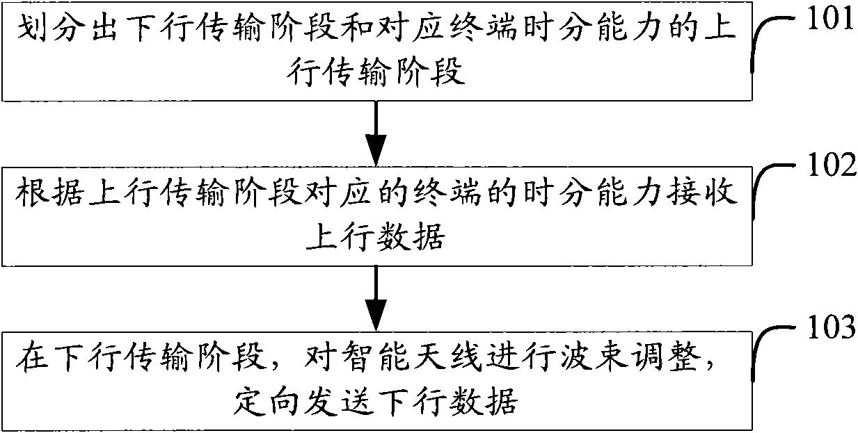
Data transmission method, access point equipment and terminal
A data transmission method and access point device technology, applied in the field of communication, can solve problems such as data loss and inability to receive data, and achieve the effect of guaranteed reception
- Summary
- Abstract
- Description
- Claims
- Application Information
AI Technical Summary
Problems solved by technology
Method used
Image
Examples
Embodiment 1
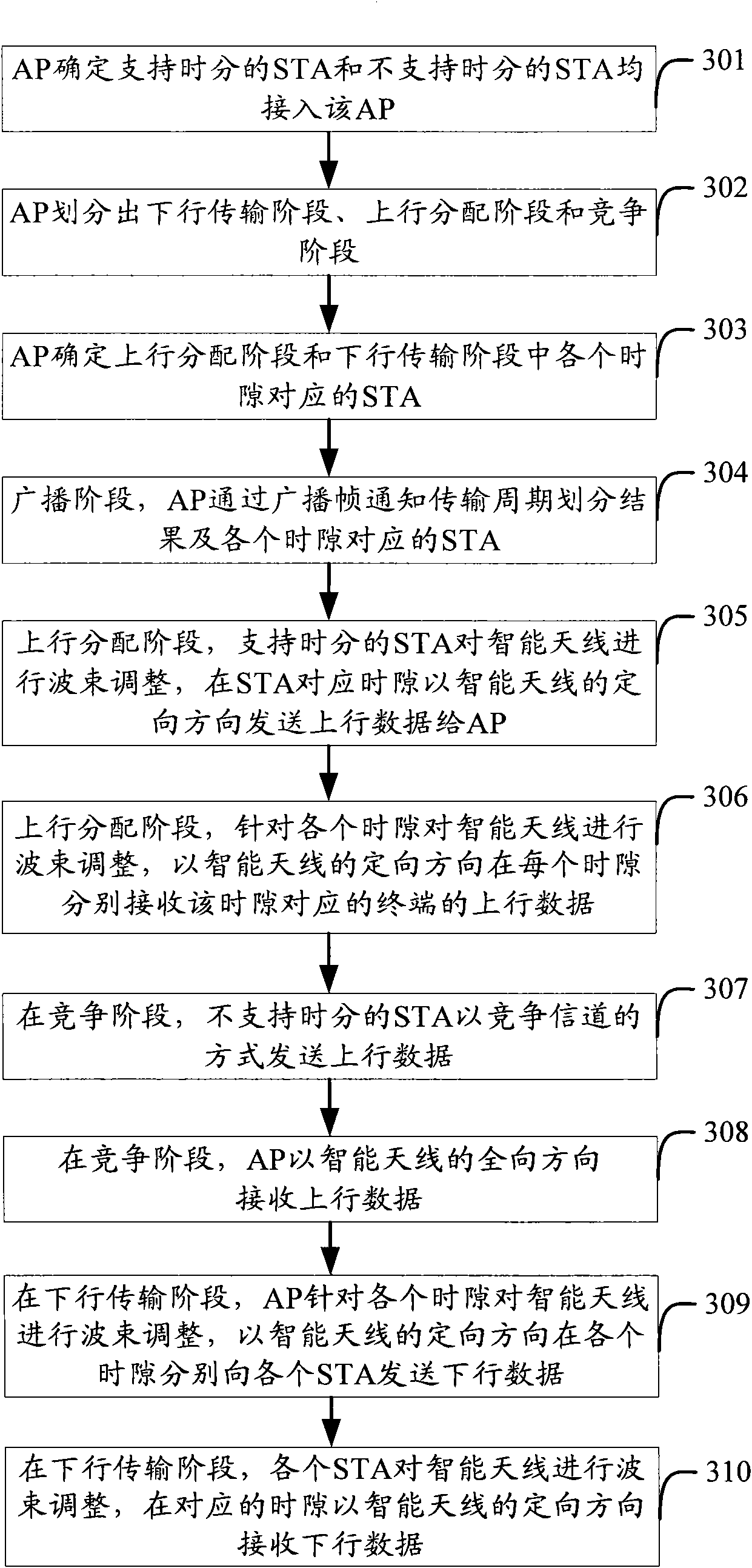
[0050] Embodiment 1 corresponds to service scenario 1. Both STAs supporting time division and STAs not supporting time division are connected to the AP. For ease of understanding, the processes in which the AP and the STA use smart antennas to transmit data respectively are described in the same process.
[0051] see image 3 In Embodiment 1 of the present invention, the process of data transmission between the AP and the STA using the smart antenna may include the following steps:
[0052] Step 301: The STA and the AP perform time division capability negotiation, and the AP determines that both STAs supporting time division and STAs not supporting time division are connected to the AP.
[0053] The time-division capability negotiation can be carried out by carrying the time-division capability bit to inform the AP whether it supports the time-division transmission function when the terminal makes a detection or association request. At the same time, the AP also carries the tim...
Embodiment 2
[0080] Embodiment 2 corresponds to service scenario 2, and only STAs that do not support time division are connected to the AP. For ease of understanding, the processes in which the AP and the STA use smart antennas to transmit data respectively are described in the same process.
[0081] see Figure 5 In Embodiment 2 of the present invention, the process of data transmission between the AP and the STA using the smart antenna may include the following steps:
[0082] Step 501: The STA and the AP perform time division capability negotiation, and the AP determines that only STAs that do not support time division are connected to the AP.
[0083] Step 502: The AP periodically divides the transmission cycle of the channel, and divides the downlink transmission phase and the uplink transmission phase corresponding to the terminal's time division capability. The uplink transmission phase is actually a competition phase used by STAs that do not support time division.
[0084] In th...
Embodiment 3
[0091] Embodiment 3 corresponds to service scenario 3, and only STAs supporting time division are connected to the AP. For ease of understanding, the processes in which the AP and the STA use smart antennas to transmit data respectively are described in the same process.
[0092] see Figure 7 In Embodiment 3 of the present invention, the process of data transmission between the AP and the STA using the smart antenna may include the following steps:
[0093] Step 701: The STA and the AP perform time division capability negotiation, and the AP determines that only STAs that support time division can access the AP.
[0094] Step 702: The AP periodically divides the transmission cycle of the channel, and divides the downlink transmission phase and the uplink transmission phase corresponding to the time division capability of the terminal. The uplink transmission phase is actually the uplink allocation phase used by STAs supporting time division.
[0095] In the third embodiment...
PUM
 Abstract
Description
Claims
Application Information
 - R&D
- Intellectual Property
- Life Sciences
- Materials
- Tech Scout
- Unparalleled Data Quality
- Higher Quality Content
- 60% Fewer Hallucinations
Browse by: Latest US Patents, China's latest patents, Technical Efficacy Thesaurus, Application Domain, Technology Topic, Popular Technical Reports.
© 2025 PatSnap. All rights reserved.Legal|Privacy policy|Modern Slavery Act Transparency Statement|Sitemap|About US| Contact US: help@patsnap.com


