Design method of double layer silicon photovoltaic cell for mobile phone battery

A mobile phone battery and silicon photovoltaic cell technology, applied in secondary batteries, circuits, photovoltaic power generation, etc., can solve the problems of no power and no charging environment for mobile phones, and achieve the effect of solving distress

Inactive Publication Date: 2012-03-21
刘崇朴
View PDF0 Cites 2 Cited by
  • Summary
  • Abstract
  • Description
  • Claims
  • Application Information

AI Technical Summary

Problems solved by technology

[0004] The purpose of the present invention is to provide a mobile phone battery that can be easily charged to solve the distress that the mobile phone has no power and no charging environment.

Method used


Image

  • Design method of double layer silicon photovoltaic cell for mobile phone battery
  • Design method of double layer silicon photovoltaic cell for mobile phone battery
  • Design method of double layer silicon photovoltaic cell for mobile phone battery

Examples


Embodiment 1

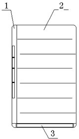
[0015] Such as figure 1 As shown, a mobile phone battery that can be easily charged includes a mobile phone battery 1, at least one side of the mobile phone battery 1 has a silicon photovoltaic cell 2, and the silicon photovoltaic battery 2 is electrically connected to the mobile phone battery 1 through a DC / DC conversion circuit 3. Charge the mobile phone battery 1 when receiving light.

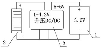
[0016] Such as figure 2 As shown, the DC / DC conversion circuit 3 is a boost conversion circuit, the input voltage is 1-4.2V, and the output voltage is 5-6V. The voltage is 0 when there is no light. Therefore, there is a diode between the output terminal of the DC / DC conversion circuit 3 and the battery 1 of the mobile phone to prevent the reverse current from affecting the silicon photocell.

[0017] The input end of the boost conversion circuit is electrically connected to the output end of the silicon photoelectric cell 2 , and the output end of the boost conversion circuit is electrica...

Embodiment 2

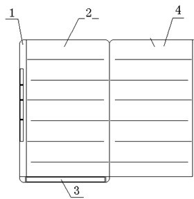
[0019] Such as image 3 As shown, the difference from Embodiment 1 is that the silicon photovoltaic cell 2 has a double-layer folded structure, and the silicon photovoltaic cell 2 of the double-layer folded structure can be unfolded to increase the area.

[0020] Since the solar cell is used as a side of the mobile phone battery, when the mobile phone is out of power, the solar cell of the mobile phone battery is faced to the direction of strong sunlight, and the light is used to make the solar cell generate photocurrent, and then the mobile phone battery is charged, although the current will not It is very large, but after charging for a period of time, the mobile phone can be turned on, view the required information, or talk to important events, and solve the distress caused by the lack of power.


PUM


Abstract

The invention relates to a silicon photovoltaic cell, particularly to a design method of a double layer silicon photovoltaic cell for a mobile phone battery, which involves a mobile phone battery. The design method is characterized in that a silicon photovoltaic cell is at least arranged on one side of the mobile phone battery, and the silicon photovoltaic cell adopts a double-folding structure which can be unfolded. The silicon photovoltaic cell is electrically connected with the mobile phone battery through a DC/DC conversion circuit for receiving liquid to charge a mobile phone. The DC/DC conversion circuit is a boosting conversion circuit, wherein the input end of the boosting conversion circuit is electrically connected with the output end of the silicon photovoltaic cell, and the output end of the boosting conversion circuit is electrically connected with the mobile phone battery. The solar cell generates light current by using light and then charges the mobile phone battery. Although the current is not very high, the mobile phone can be turned on after being charged for a while, so that a user can browse required information or make a call to persons involves in an important event, and the trouble arising from battery dying is solved.

Description

technical field [0001] The invention relates to a silicon photovoltaic cell, in particular to a design method for a double-layer silicon photovoltaic cell used in a mobile phone battery. Background technique [0002] With the mobile phone entering the 3G era, the powerful functions of the mobile phone make the mobile phone a mobile computer or office equipment. The increase of functions needs to be equipped with large hardware support, and finally needs to be powered by batteries. [0003] Existing batteries or high-capacity batteries are only 1-2A, which is not enough to support 2-3 days of use. Due to the busy work of modern people, sometimes the mobile phone cannot be charged in time. When talking, the mobile phone is out of power, which brings great inconvenience to life. When there is no charging environment, it is very distressing. Contents of the invention [0004] The purpose of the present invention is to provide a mobile phone battery that can be easily charge...

Claims


Application Information

Patent Timeline
Patent Type & Authority Applications(China)
IPC IPC(8): H01M10/46H01L31/045
CPCY02E10/50Y02E60/12Y02E60/10
Inventor 刘崇朴段重阳刘明
Owner 刘崇朴
Why Eureka
Try Eureka