Band saw
A technology of band saws and band saw blades, which is applied in the direction of sawing machine devices, metal sawing equipment, metal processing equipment, etc., can solve problems such as wear and rib wear, and achieve the effect of reducing wear and friction
- Summary
- Abstract
- Description
- Claims
- Application Information
AI Technical Summary
Problems solved by technology
Method used
Image

Examples
no. 1 approach
[0043] Hereinafter, an embodiment of a band saw for carrying out the present invention will be described with reference to the drawings.
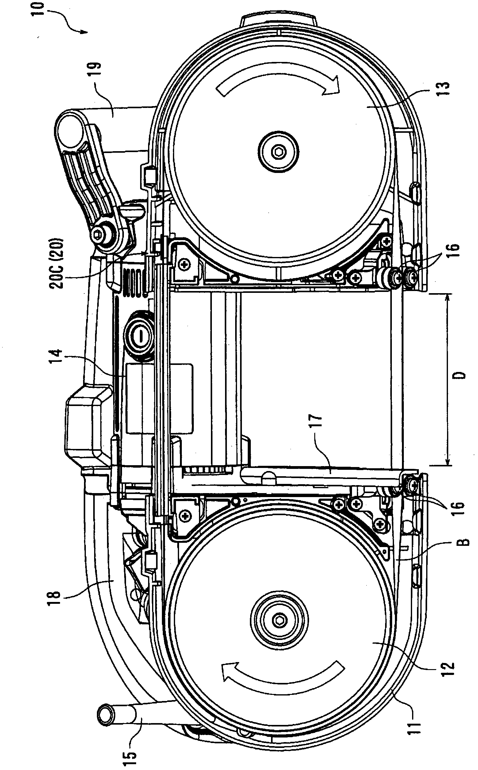
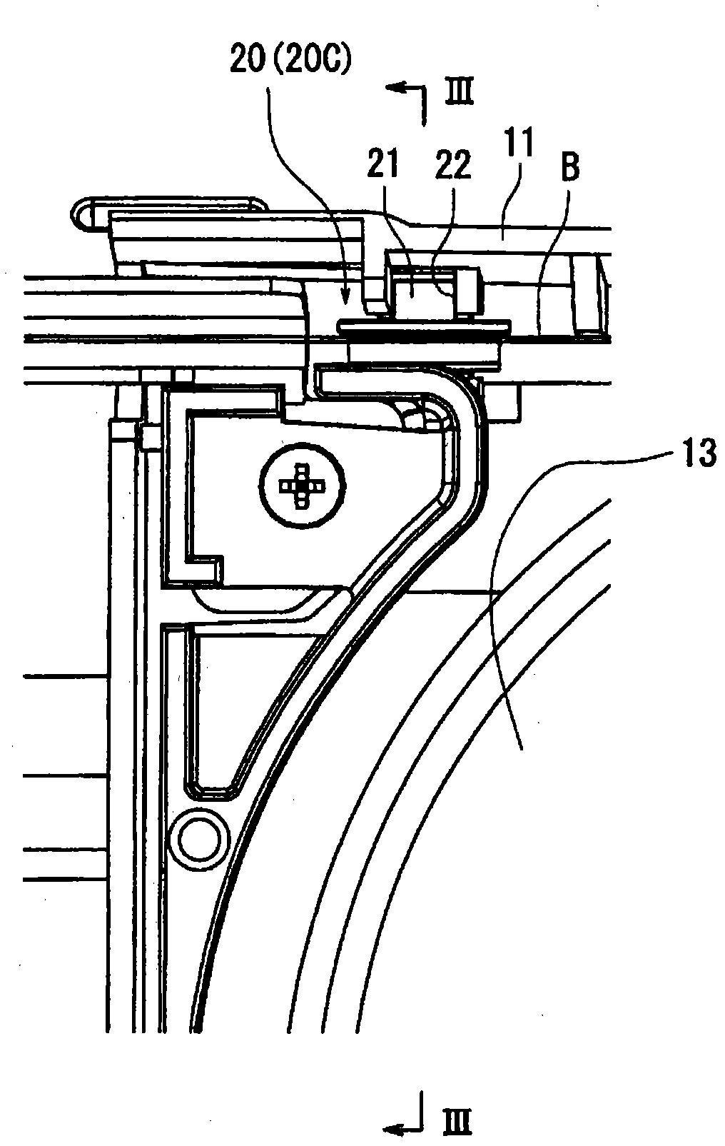
[0044] figure 1 The band saw 10 shown in , cuts the material to be cut by making the band saw blade B in the shape of an endless band perform a circular motion. figure 2 is zoomed in from figure 1 A rear view of the movable guide mechanism 20 viewed from the back side of FIG. also, figure 1 as well as figure 2 The movable guide mechanism 20 shown is a movable guide mechanism 20C of a third embodiment described later.
[0045] figure 1 The band saw 10 shown is a widely used portable band saw also called a portable band saw (portable band saw). Therefore, although the overall view of the band saw 10 is only figure 1 , but the configuration of the band saw 10 is the same as that of the widely used portable band saw. That is, if figure 1 As shown, the band saw 10 generally has: a housing 11 ; a pair of saw wheels 12 , 13 ; and a driv...
no. 2 approach
[0068] Next, a movable guide mechanism 20B ( 20 ) as a second embodiment will be described.
[0069] Figure 5 It is an enlarged cross-sectional view showing the movable guide mechanism 20B of the second embodiment. Image 6 is further enlarged to display Figure 5 A cross-sectional view of the movable guide mechanism 20B in . In addition, the movable guide mechanism 20B as this second embodiment differs from the movable guide mechanism 20A as the above-mentioned first embodiment only in the configuration of the outer ring 45 of the bearing 40 . Therefore, the configuration related to the outer ring 45 will be mainly described, and the configurations other than the outer ring 45 will be given the same reference numerals as above, and the description will be simplified.
[0070] Figure 5 as well as Image 6 The bearing 40 of the second embodiment shown is the same as the above-mentioned first embodiment, and is composed of a widely used "sliding bearing", which has an inn...
no. 3 approach
[0076] Next, a movable guide mechanism 20C ( 20 ) as a third embodiment will be described.
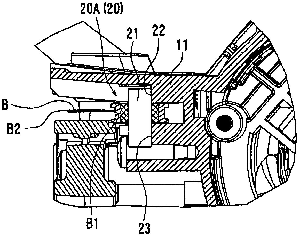
[0077] Figure 7 It is an enlarged cross-sectional view showing the movable guide mechanism 20C of the third embodiment. Figure 8 is to further enlarge the display Figure 7 A cross-sectional view of the movable guide mechanism 20C in FIG. In addition, the movable guide mechanism 20C which is this 3rd embodiment differs only in the structure concerning the bearing 50 compared with the movable guide mechanisms 20A, 20B which are the said 1st, 2nd embodiment. Therefore, the configuration related to the bearing 50 will be mainly described, and the configurations other than the bearing 50 will be given the same reference numerals as above, and the description will be simplified.
[0078] Figure 7 as well as Figure 8 The bearing 50 of the third embodiment shown is different from the above-mentioned first and second embodiments in that it is composed of a widely used "rolling bearing...
PUM
 Abstract
Description
Claims
Application Information
 - R&D
- Intellectual Property
- Life Sciences
- Materials
- Tech Scout
- Unparalleled Data Quality
- Higher Quality Content
- 60% Fewer Hallucinations
Browse by: Latest US Patents, China's latest patents, Technical Efficacy Thesaurus, Application Domain, Technology Topic, Popular Technical Reports.
© 2025 PatSnap. All rights reserved.Legal|Privacy policy|Modern Slavery Act Transparency Statement|Sitemap|About US| Contact US: help@patsnap.com