
Mechanical latching mechanism of explosion-proof switching box

A mechanical lock and switch box technology, applied in the direction of electrical switches, electrical components, circuits, etc., can solve the problems of complicated operation, damage and misoperation of maintenance personnel, etc., to prevent coal mine gas and dust explosion, reasonable structure design, Ensure the effect of construction safety

Active Publication Date: 2012-02-22
久益环球(青岛)电气有限公司
View PDF5 Cites 8 Cited by
  • Summary
  • Abstract
  • Description
  • Claims
  • Application Information

AI Technical Summary

Problems solved by technology

The existing switch box structure can open the left and right doors when the isolating switch is electrified, which can easily cause misoperation by maintenance personnel, electric shock accidents, and even gas and coal dust explosion accidents
Most of the existing technologies use electromechanical combined locking, which has the problem of low reliability and damage. For example, the patent No.: 200720016697.7 and the patent name: "Explosion-proof control box for electromechanical combined locking" discloses a mine The locking device of the explosion-proof control box used by the air compressor, but the key components of this locking device are buttons, wrenches, switches, screw screws and limit plates. The locking structure of this structure is complex to operate, easy to damage, and safe and reliable. Sex is not high

Method used


Image

  • Mechanical latching mechanism of explosion-proof switching box
  • Mechanical latching mechanism of explosion-proof switching box
  • Mechanical latching mechanism of explosion-proof switching box

Examples


specific Embodiment approach

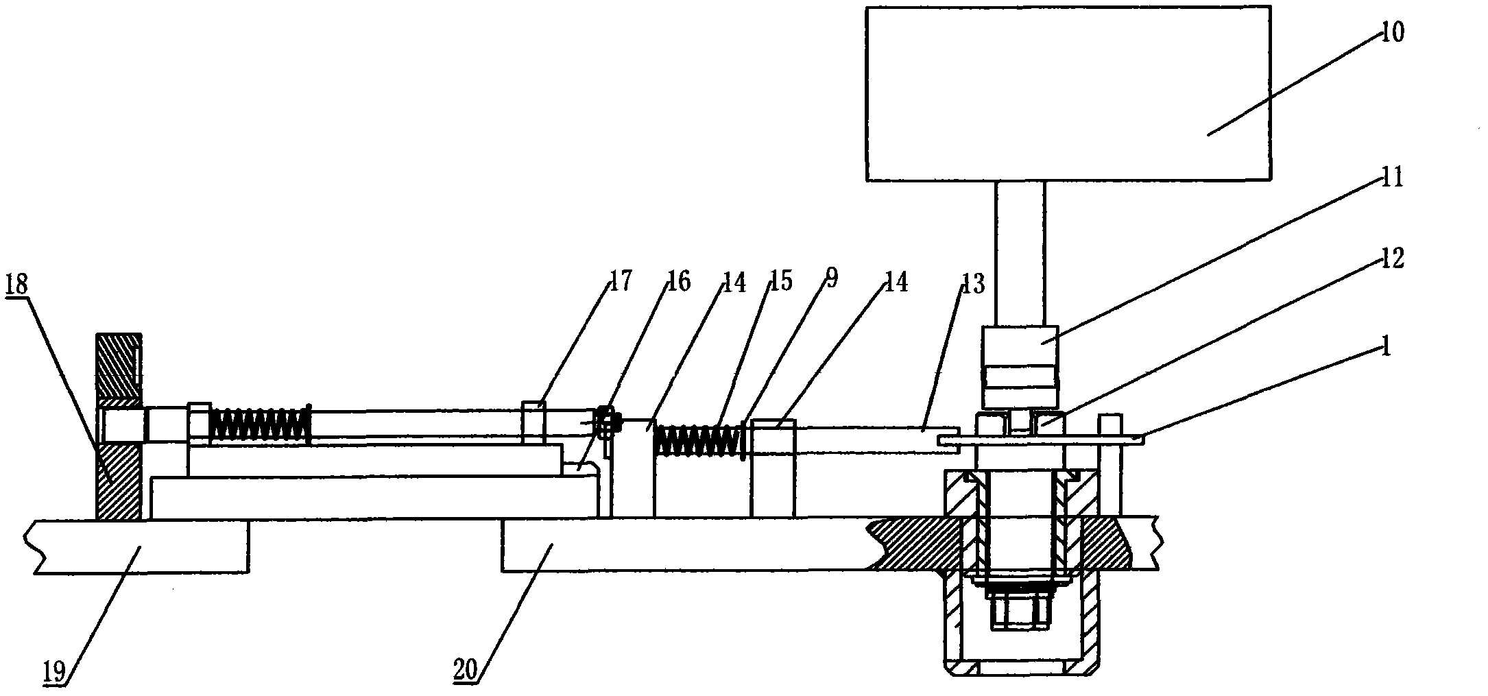
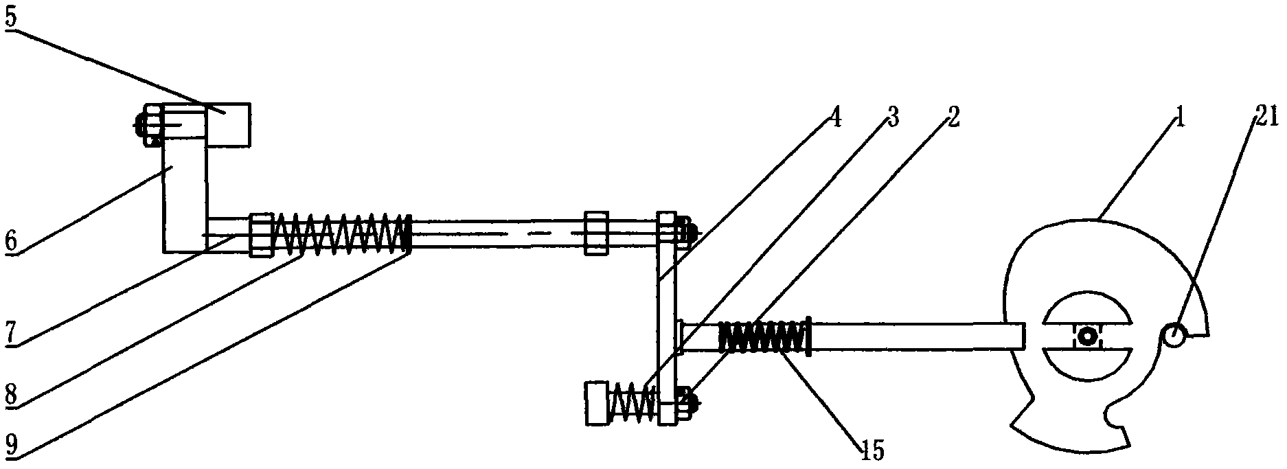
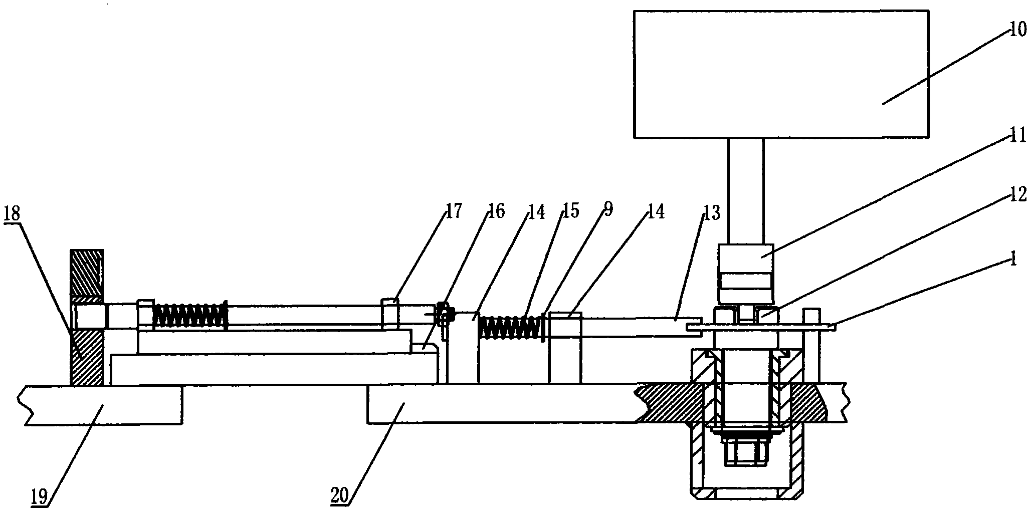
[0013] A mechanical locking mechanism for a flameproof switch box, which is arranged on the inner side of the left door 19, the inner side of the right door 20, and the inner side of the box between the left door 19 and the right door 20, and the inner side of the right door 20 is provided with a rotating shaft 12 , locking limit plate 1, right door locking lever 13 and right door locking shaft seat 14, described rotating shaft 12 is rotatably installed on the right door 20, and rotating shaft 12 is connected with the isolating switch 10 in the casing after the right door 20 is closed. The operating rod 11 is connected to the rotating shaft 12, and the operating handle is connected to the rotating shaft 12. The working state of the isolating switch 10 can be controlled through the operating handle. The rotation of the bit plate 1 can drive the left and right movement of the right door locking lever 13, thereby controlling the opening and closing of the locking mechanism; the ri...


PUM


Abstract

The invention relates to a mechanical latching mechanism of an explosion-proof switching box. Mechanical latching mechanisms are arranged at an inner side of a left door, an inner side of a right door and an inner side of a box body between the left door and the right door. A rotating shaft, a latching limit disk, a right-door latching lever, and a right-door latching axle seat are arranged at the inner side of the right door. A latching backing plate, an intermediate axle seat, an intermediate pin, a latching board guiding axle and a latching board are arranged at the inner side of the box body. Besides, a left-door latching hammer base is arranged at the inner side of the box body; and a left-door latching hammer is rotatably installed at the left-door latching hammer base. Moreover, a left-door latching base is arranged at the inner side of the left door, wherein the position of the left-door latching base is corresponded to that of the left-door latching hammer base; and an intermediate pin hole that is corresponded to the intermediate pin is arranged on the left-door latching base. According to the invention, latching mechanisms are utilized to control breaking of an isolating switch, so that misoperation of operation personnel and maintenance personnel can be prevented and construction safety can be ensured; and therefore, possibilities of gas and dust explosion in a coal mine can be eliminated, wherein the gas and dust explosion may be caused by the misoperation.

Description

technical field [0001] The invention relates to a safety protection device for a flameproof switch box, in particular to a locking mechanism arranged on the inner side of the left door of the switch box, the inner side of the right door and the inner side of the box body between the left door and the right door. Background technique [0002] The working environment of the underground equipment in the coal mine is harsh, and the left and right doors of the switch box must be opened for maintenance when the equipment fails and the specified maintenance period is reached. The existing switch box structure can open the left and right doors when the isolating switch is electrified, which can easily cause misoperation by maintenance personnel, electric shock accidents, and even gas and coal dust explosion accidents. Most of the existing technologies use electromechanical combined locking, which has the problem of low reliability and damage. For example, the patent No.: 20072001669...

Claims


Application Information

Patent Timeline
Patent Type & Authority Applications(China)
IPC IPC(8): H01H9/22
Inventor 韩业瑞
Owner 久益环球(青岛)电气有限公司
Learn More