Eureka AIR delivers breakthrough ideas for toughest innovation challenges, trusted by R&D personnel around the world.

Multifunctional double-drum filter valve

A technology of filter valve and double cylinder, which is applied in the direction of filter separation, valve device, mechanical equipment, etc., and can solve the problems of unreliable sealing, switching valve and valve seat without sealing structure, inconvenient online cleaning work, etc.

Active Publication Date: 2012-02-22
正球阀门集团有限公司
View PDF5 Cites 7 Cited by
  • Summary
  • Abstract
  • Description
  • Claims
  • Application Information

AI Technical Summary

Problems solved by technology

However, the existing double-barrel filter valve diversion switching valve usually adopts a three-way reversing valve, a ball valve, etc., and the above-mentioned diversion switching valve is sealed and connected with the valve seat in a rotating and cut-in manner to realize blockage or connection of the pipeline. The pressing force between the switch valve and the valve seat is limited, and the seal is unreliable; and there is no reliable sealing structure between the existing switch valve and the valve seat, and only one end surface in contact with each other forms a seal (for example, the patent number is CN03207477 .8 patent document), in this case, the liquid is easy to leak, and the split switching valve cannot completely cut off the liquid of the other filter cartridge, which brings inconvenience to the online cleaning work, and in severe cases, the online cleaning work will not be possible

Method used


Image

  • Multifunctional double-drum filter valve
  • Multifunctional double-drum filter valve
  • Multifunctional double-drum filter valve

Examples


Embodiment Construction

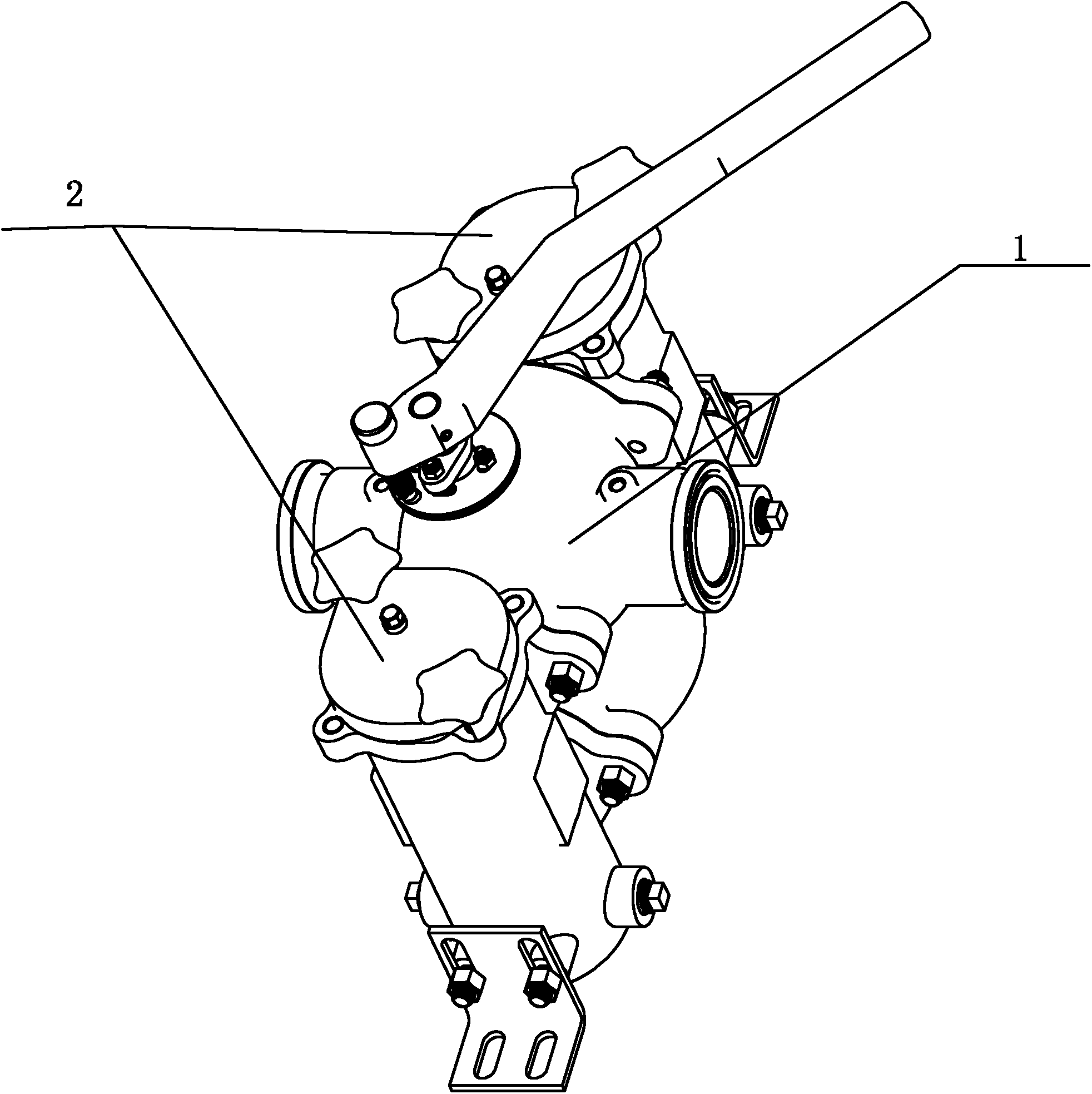
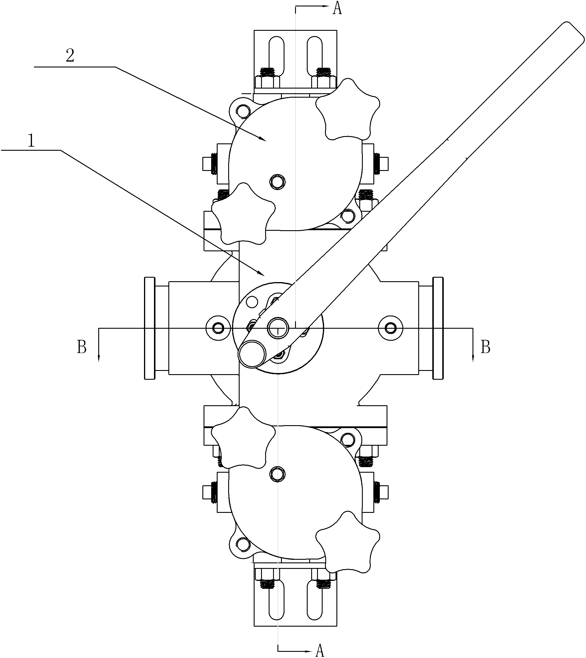
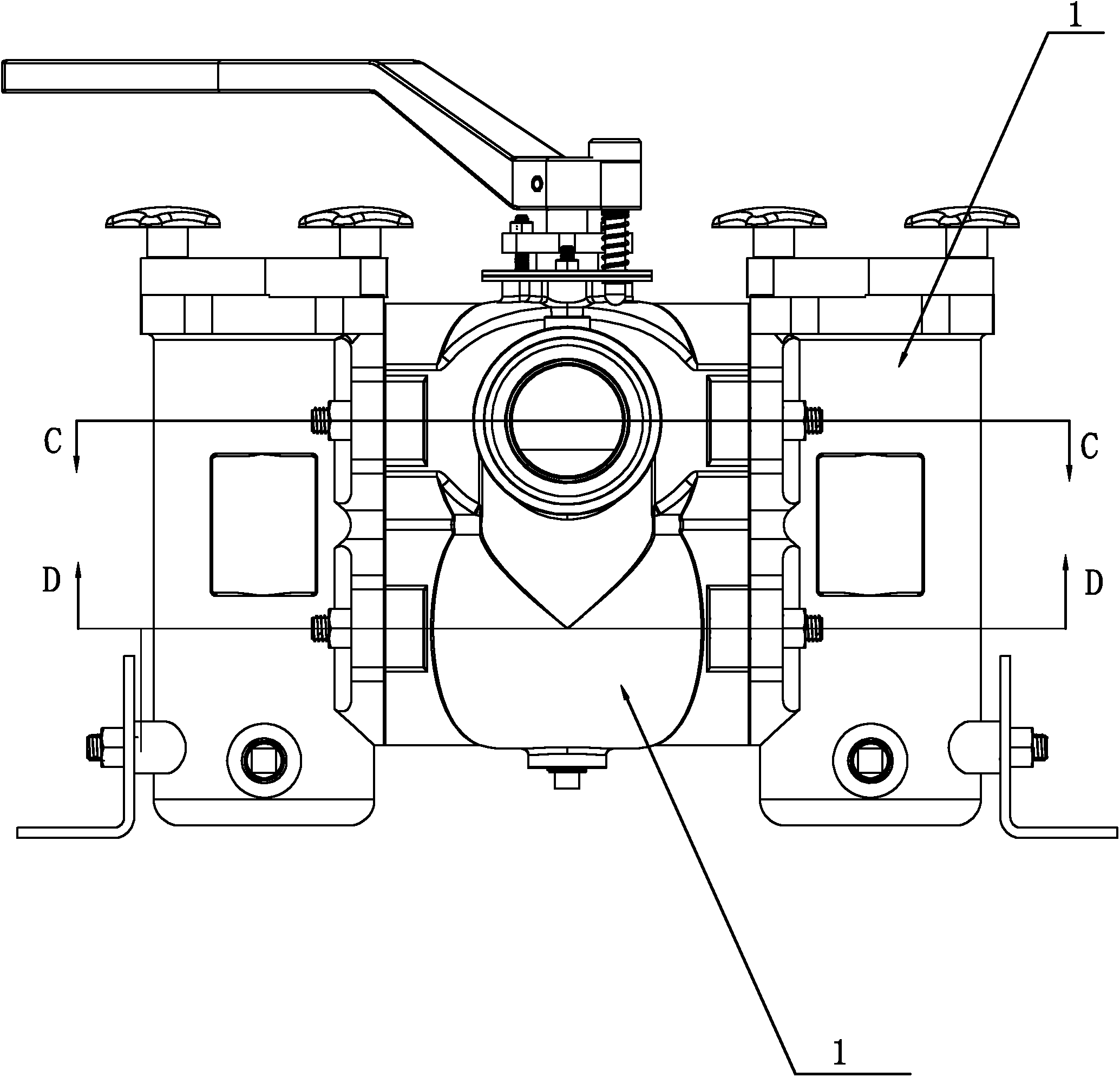
[0027] See attached figure 1 To attach Figure 11 , a double cylinder filter valve disclosed by the present invention includes a valve body 1, a fluid inlet 11 and a fluid outlet 12 arranged on the valve body 1; the top of the valve body 1 is provided with a valve shaft mounting seat, and the valve There is a stepped hole in the center of the shaft mounting seat, and several positioning blind holes are arranged around the periphery of the stepped hole; a valve cavity is provided in the valve body, and a baffle plate 15 is arranged in the valve cavity, and the baffle plate 15 separates the valve cavity into mutually independent parts. Upper and lower valve chambers 13, 14, the upper valve chamber 13 communicates with the fluid inlet 11, and the lower valve chamber 14 communicates with the fluid outlet 12; the baffle plate 15 is provided with a valve coaxial with the stepped hole on the valve shaft mounting seat. Shaft positioning mounting hole, one end of the valve shaft 3 pa...


PUM


Abstract

The invention relates to a double-drum filter valve, wherein an included angle Alpha which is matched with the rotation angle of an upper plunger valve is formed between the central axis of the seal end of a valve seat a and the central axis of the seal end of a valve seat b in an upper valve cavity; an included angle Beta which is matched with the rotation angle of a lower plunger valve is formed between the central axis of the valve port seal end of a valve seat c and the central axis of the valve port seal port of a valve seat d in a lower valve cavity; and the included angle Alpha and theincluded angle Beta are both 90 DEG. Due to the setting of the included angles, the clamping force between the valve and the valve seats is increased, and the sealing performance is improved; in addition, a seal ring is arranged on the seal end of each valve seat, two axial ends of the upper plunger valve and the lower plunger valve are respectively provided with a ceramic cup-cover-shaped seal structure which forms plug seal to the seal ends of the valve seats, and a positioning flange on each seal structure is in a shape of a cone which is narrowed along the free end. With the structure design, when the plunger valve and the valve seats are sealed, double seal surface seal of end surface and lateral surface is formed, and the plug seal is more reliable; and when a single filtering drum works, a filtering drum which does not work cannot generate liquid leakage.

Description

technical field [0001] The invention relates to a fluid filter device, in particular to a filter valve, in particular to a multi-functional double cylinder filter valve. Background technique [0002] The traditional filter valve is a single cylinder filter valve. During the working process, when the filter element of the single cylinder filter valve is clogged to a certain extent and needs to be cleaned or replaced, the main engine must be stopped to replace the filter element, which not only wastes time but also cannot meet the continuous working needs of the main engine. . [0003] In order to solve the defects of the single cylinder filter valve, people designed the double cylinder filter valve, which effectively solved the defect of the single cylinder filter valve; through the diversion switching valve, the conversion of the left and right working areas of the double cylinder filter valve is realized, and the online Clean the filter cartridge in non-working state. How...

Claims


Application Information

Patent Timeline
Patent Type & Authority Applications(China)
IPC IPC(8): F16K51/00B01D35/02B01D35/12
Inventor 王明华胡理良谭克平谭克勇陈林
Owner 正球阀门集团有限公司
Why Eureka
Eureka Blog
Learn More