
Planar magnetic drive coupler

A magnetic transmission and coupler technology, applied in the field of magnetic coupling, can solve problems that cannot be overcome and affect the normal operation of the planar magnetic transmission coupler

Active Publication Date: 2012-02-15
兰州海兰德泵业有限公司
View PDF6 Cites 12 Cited by
  • Summary
  • Abstract
  • Description
  • Claims
  • Application Information

AI Technical Summary

Problems solved by technology

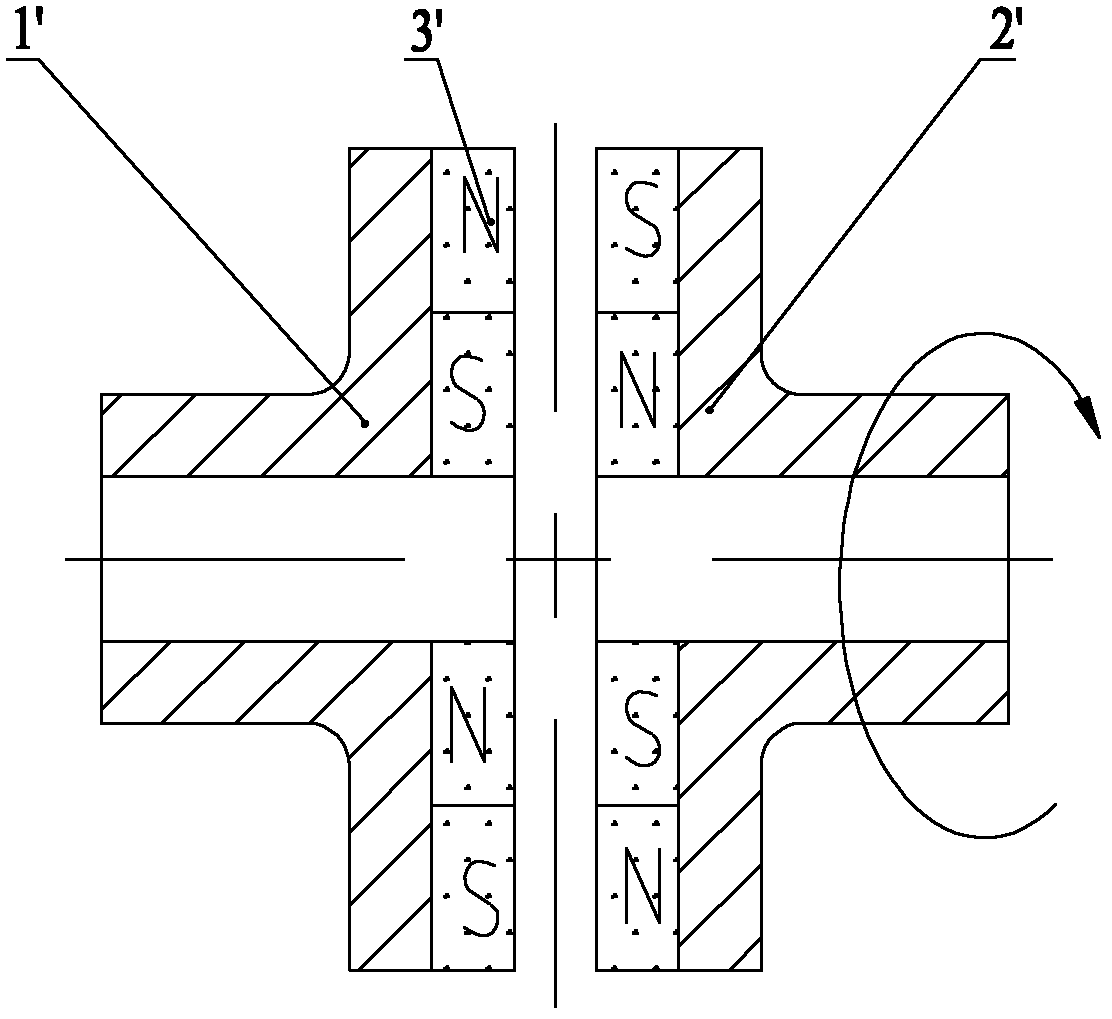
[0008] The planar magnetic drive coupler with this structure is technically unable to overcome the harmful axial force F 轴向 , the axial force F 轴向 Will affect the normal work of the planar magnetic drive coupler

Method used


Image

  • Planar magnetic drive coupler
  • Planar magnetic drive coupler
  • Planar magnetic drive coupler

Examples


Embodiment Construction

[0032] In order to enable those skilled in the art to better understand the technical solutions of the present invention, the present invention will be further described in detail below in conjunction with the accompanying drawings and specific embodiments.

[0033] Please see Figure 5-Figure 7 , Figure 5 A schematic structural view of a specific embodiment of the planar magnetic drive coupling provided by the present invention; Figure 6 for Figure 5 Schematic diagram of the structure of the driven magnetic disk; Figure 7 for Figure 5 Schematic diagram of the structure of the active magnetic disk.

[0034] Such as Figure 5-Figure 7 As shown, the planar magnetic transmission coupler provided by the present invention includes an active magnetic disk 8 and a driven magnetic disk 1 which are arranged oppositely. A magnetic circuit 5, the driven disk is provided with a driven levitation magnetic circuit 2, a driven circumferential torsion magnetic circuit 4, the active...


PUM


Abstract

The invention relates to the technical field of magnetic coupling and discloses a planar magnetic drive coupler. The coupler comprises a driving magnetic disc and a driven magnetic disc, which are oppositely arranged, wherein the driving disc is radially provided with driving levitated magnetic circuits and driving circumferential torsion magnetic circuits from inside to outside in sequence; the driven disc is radially provided with driven levitated magnetic circuits and driven circumferential torsion magnetic circuits from inside to outside in sequence; the driving levitated magnetic circuits align at the driven levitated magnetic circuits; and the driving circumferential torsion magnetic circuits align at the driven circumferential torsion magnetic circuits. The planar magnetic drive coupler with such a structure has the following beneficial effects that: as the levitated magnetic circuits arranged in close push-pull combination are arranged on the driving magnetic disc and the driven magnetic disc respectively, when the driving magnetic disc carries out translation, the levitated magnetic circuits can overcome the harmful axial forces generated by the circumferential torsion magnetic circuits axially so that torsion and forces can be stably driven between the driving magnetic disc and the driven magnetic disc in a contactless manner.

Description

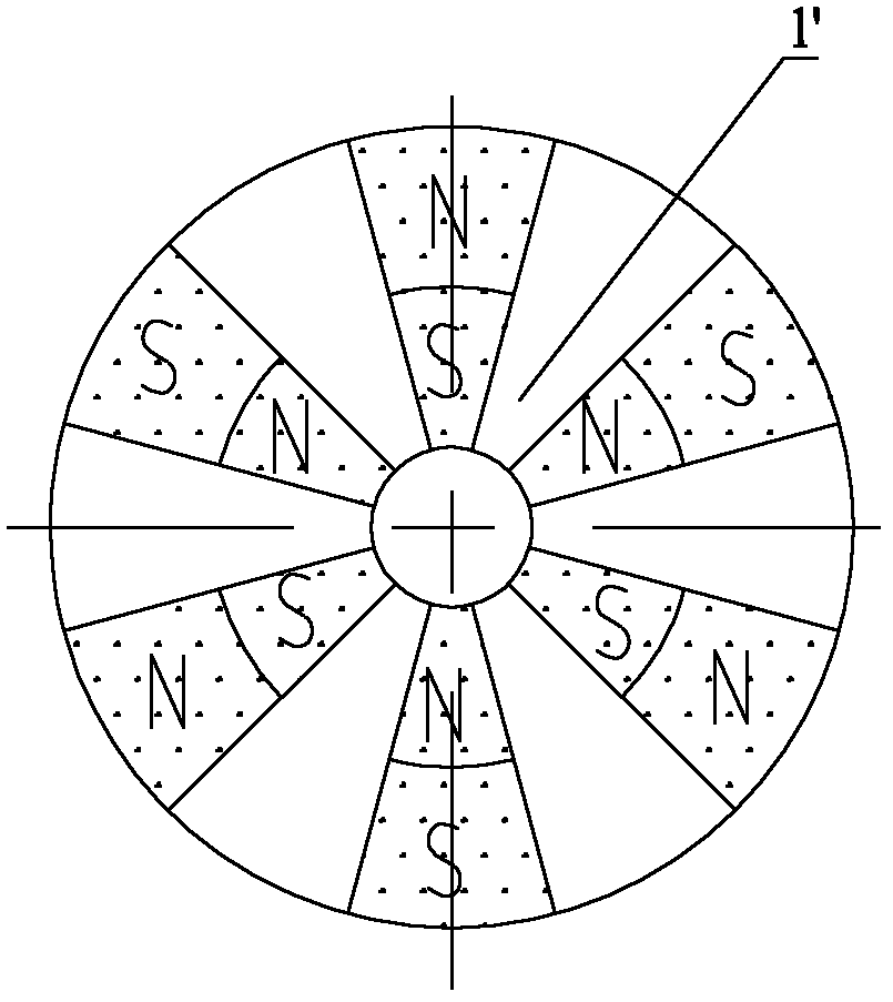
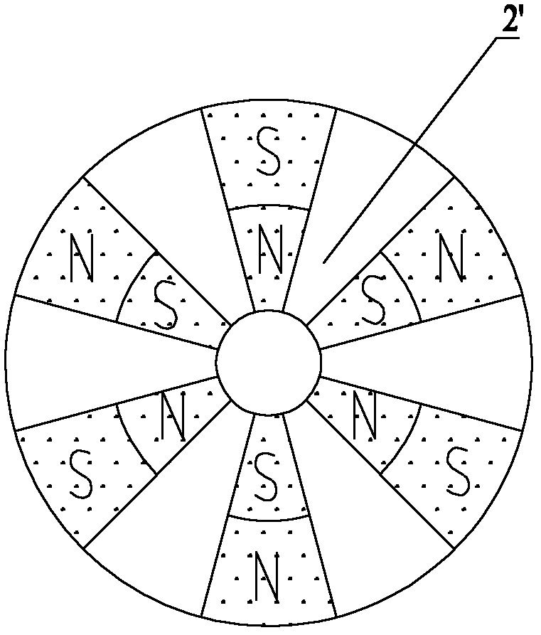
technical field [0001] The invention relates to the technical field of magnetic coupling, in particular to a planar magnetic force transmission coupler. Background technique [0002] With the substantial improvement of the performance of permanent magnet materials, the over-distance coupling characteristics of permanent magnet materials have been widely used in various transmission mechanisms, such as magnetic couplings. [0003] A planar magnetic transmission coupler is a common magnetic coupler, and the planar magnetic coupler in the prior art will be briefly introduced below. [0004] Please see Figure 1-Figure 3 , figure 1 It is a structural schematic diagram of a typical planar magnetic drive coupler in the prior art; figure 2 for figure 1 Schematic diagram of the structure of the driven disk; image 3 for figure 1 Schematic diagram of the structure of the active magnetic disk. [0005] Such as Figure 1-Figure 3 As shown, the planar magnetic transmission cou...

Claims


Application Information

Patent Timeline
IPC IPC(8): H02K51/00H02N15/00
Inventor 殷春红崔国平豆耀峰刘挺
Owner 兰州海兰德泵业有限公司
Learn More