Controller for and method of controlling internal combustion engine
一种内燃机控制、内燃机的技术,应用在内燃活塞发动机、电气控制、燃烧发动机等方向,能够解决传感器结构复杂、降低实用性等问题
- Summary
- Abstract
- Description
- Claims
- Application Information
AI Technical Summary
Problems solved by technology
Method used
Image

Examples
no. 1 example
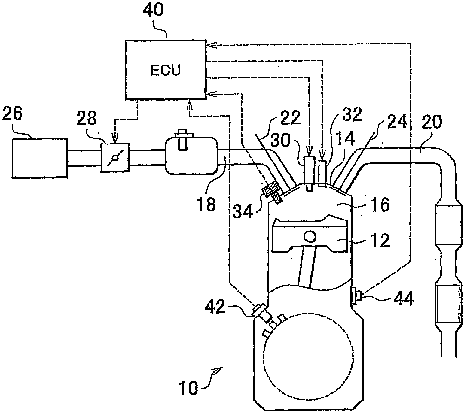
[0082] figure 1 A schematic configuration diagram illustrating the system configuration of the first embodiment of the present invention is shown. like figure 1 As shown, the system of this embodiment is provided with an internal combustion engine 10 . The internal combustion engine 10 is a spark ignition engine using gasoline as fuel. In a cylinder of the internal combustion engine 10, a piston 12 reciprocating inside the cylinder is provided. Internal combustion engine 10 also includes a cylinder head 14 . Combustion chamber 16 is formed between piston 12 and cylinder head 14 . One end of the intake passage 18 and one end of the exhaust passage 20 are connected to the combustion chamber 16 . An intake valve 22 and an exhaust valve 24 are respectively provided at a connection portion between the combustion chamber 16 and the intake passage 18 and a connection portion between the combustion chamber 16 and the exhaust passage 20 .
[0083] An air filter 26 is installed at...
no. 2 example
[0132] Next, we will refer to Figure 9 to Figure 11 Features of the second embodiment are described. The second embodiment is by using figure 1 The hardware shown, implements the Figure 10 The routine shown is implemented.
[0133] In the above-mentioned system of the first embodiment, it is assumed that the PV κ The value of is essentially constant during the adiabatic process after combustion to correct for thermal strain errors. This assumption holds true when the internal combustion engine 10 is fully warmed up and operating normally, and therefore, thermal strain errors can be accurately corrected using the system of the first embodiment described above. However, in the internal combustion engine 10, cooling loss occurs due to low water temperature, low engine speed, etc. before the engine is warmed up. Figure 9 is showing the cooling loss vs. PV κ A plot of the effect of the value of . Figure 9 The curve indicated by L4 in , represents the PV at an engine spee...
no. 3 example
[0148] Next, we will refer to Figure 12 and Figure 13 Features of the third embodiment are described. The third embodiment is by using figure 1 The hardware shown, implements the Figure 13 The routine shown is implemented.
[0149] In the system of the first embodiment described above, thermal strain errors are corrected during the adiabatic process after combustion (see Image 6 ). The direct injection noise, ignition noise, etc. of another cylinder will be superimposed on the cylinder pressure P. Thus, the farther the crank angle is from top dead center (TDC), the larger the cylinder volume V is, amplified and superimposed as an error factor on the calculated PV κ The greater the noise on the value of . The system of the first embodiment described above cannot correct errors caused by such noise.
[0150] Thus, in the system of the third embodiment, the error due to the thermal strain of the cylinder pressure sensor 34 and the error due to the above-mentioned nois...
PUM
 Abstract
Description
Claims
Application Information
 - R&D
- Intellectual Property
- Life Sciences
- Materials
- Tech Scout
- Unparalleled Data Quality
- Higher Quality Content
- 60% Fewer Hallucinations
Browse by: Latest US Patents, China's latest patents, Technical Efficacy Thesaurus, Application Domain, Technology Topic, Popular Technical Reports.
© 2025 PatSnap. All rights reserved.Legal|Privacy policy|Modern Slavery Act Transparency Statement|Sitemap|About US| Contact US: help@patsnap.com