
Multifunctional threshing machine

A threshing machine, multi-functional technology, applied in threshing equipment, agricultural machinery and implements, applications, etc., can solve the problems of single function, inconvenient efficiency, large shedding, etc., and achieve the effect of improving threshing efficiency

Inactive Publication Date: 2012-02-08
CHENGDU JINCHUANTIAN AGRI MACHINE MFG
View PDF3 Cites 3 Cited by
  • Summary
  • Abstract
  • Description
  • Claims
  • Application Information

AI Technical Summary

Problems solved by technology

[0002] At present, most of the threshers used by people can only be used for threshing large grain crops such as rice and wheat. For bean crops such as rape and peas, it is difficult to remove them from the crop stems, and the function is relatively single.
However, when the existing thresher is in use, it is fed from the feeding port on the top of the thresher frame, and it is necessary to forcefully press the crop stem on the threshing drum to drop the crops, which is very inconvenient and inefficient. , at the same time, because the feeding port of the existing threshing machine is at the top, the shedding generated during threshing is very large
There are also some threshers for rape and peas on the market, but it is difficult for these threshers to remove the crop fruits, and the unremoved crops are also discharged from the slag outlet along with the waste, causing great damage. waste

Method used


Image

  • Multifunctional threshing machine
  • Multifunctional threshing machine
  • Multifunctional threshing machine

Examples


Embodiment

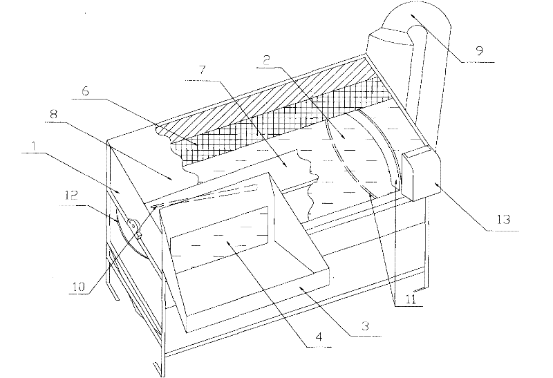
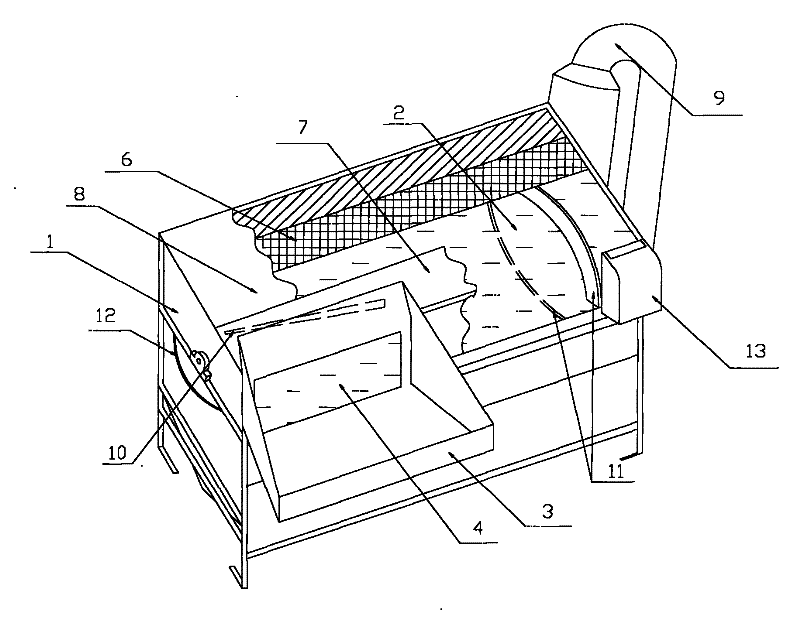
[0010] Example: see figure 1 , figure 2 , the present invention comprises a frame 1 open above, a feeding hopper 3, a separator 9, a slag outlet 13, a threshing drum 2 and a lower screen 5 below the threshing drum 2, the lower screen 5 is in a semicircular arc shape, The threshing drum 2 is evenly provided with a number of bow teeth, the feeding hopper 3 is fixedly connected to the front of the frame 1 near the left end, and the front of the frame 1 is provided with a through hole 4 communicating with the feeding hopper 3, and the lower sieve The net 5 is detachably connected with the frame 1, and the side of the frame 1 is provided with an arc-shaped gap 12 matched with the lower screen 5, and two slide rails are arranged in the frame 1, and the two slide rails are connected with the frame. 1 is fixedly connected and one end of the two slide rails is in communication with the arc-shaped gap 12, the lower screen 5 can be inserted into the chute through the arc-shaped gap 12,...


PUM


Abstract

The invention discloses a multifunctional threshing machine, which comprises a frame with an open upper part, a feeding hopper, a separator, a residue discharge hole, a threshing cylinder and a lower screen below the threshing cylinder, wherein the feeding hopper is fixedly connected to the front side of the frame close to the left end; the front side of the frame is provided with a through hole communicated with the feeding hopper; an upper screen is arranged above the threshing cylinder; the upper screen can cover the upper half part of the threshing cylinder; a movable cover plate is arranged above the upper screen; a fixed cover plate is arranged at one side of the movable cover plate close to the feeding hopper; the fixed cover plate is provided with a guide plate at a feeding hole; and an arc-shaped partition plate is respectively arranged at the upper part and the lower part of the right side of the cylinder, the two partition plates are staggered, the partition plates are positioned between two adjacent columns of arc teeth of the threshing cylinder, and two ends of the partition plates are fixedly connected with the frame respectively. The multifunctional threshing machine can be applied to various crops, is convenient to use, and has high efficiency and little waste.

Description

technical field [0001] The invention relates to a thresher, in particular to a multifunctional thresher. Background technique [0002] Most of the threshers currently used by people can only be used for threshing large grain crops such as rice and wheat. For bean crops such as rapeseed and peas, it is difficult to come off from the crop stem, and the function is relatively single. However, when the existing thresher is in use, it is fed from the feeding port on the top of the thresher frame, and it is necessary to forcefully press the crop stem on the threshing drum to drop the crops, which is very inconvenient and inefficient. , Simultaneously, because the feeding mouth of existing thresher is above, the shedding that makes when threshing produces is very large. There are also some threshers for rape and peas on the market, but it is difficult for these threshers to remove the crop fruits, and the unremoved crops are also discharged from the slag outlet along with the wast...

Claims


Application Information

Patent Timeline
IPC IPC(8): A01F7/02A01F12/00
Inventor 杨齐连
Owner CHENGDU JINCHUANTIAN AGRI MACHINE MFG
Learn More