
Automatic assembly of lamp base and energy-saving lamp using the lamp base

An automatic assembly and lamp cap technology, which is applied to the parts of gas discharge lamps, discharge lamps, discharge tubes, etc., can solve the problems of inability to realize automatic mechanical assembly, relying on labor, and single connection method.

Inactive Publication Date: 2016-11-23
LEEDARSON LIGHTING XIAMEN
View PDF5 Cites 0 Cited by
  • Summary
  • Abstract
  • Description
  • Claims
  • Application Information

AI Technical Summary

Problems solved by technology

However, existing energy-saving lamps have the problem of low assembly efficiency of lamp caps.
As disclosed on September 10, 2003, the Chinese utility model patent with the patent application number CN02269941.4 discloses a method for fastening the lamp cap assembly and the lamp tube assembly. The lamp cap assembly is provided with a card slot, and the elastic hook is used to buckle in the card slot to realize the fixed connection between the lamp cap assembly and the lamp tube assembly; although the technical solution realizes the connection between the lamp cap assembly and the lamp tube assembly, the connection method has the following defects : 1. Mechanical automatic assembly cannot be realized, it must rely on manual work, and when workers assemble the lamp cap assembly and lamp tube assembly, they must accurately align the hooks with the slots, otherwise they cannot be fastened, and the requirements for fastening accuracy are high. It affects the assembly efficiency; 2. The connection method is relatively simple, and can only rely on the cooperation of the hook and the slot, that is, the lamp can only be fixed in the axial direction, so it is difficult to ensure the stability of the connection in other directions, such as the lamp head assembly and the lamp tube The assembly is easy to rotate relatively in the radial direction, so that the wire is twisted; 4. Because the lamp head assembly and the lamp assembly are connected through the elastic fit of the hook and the groove, the stability of the connection depends on the elasticity of the hook. If the elastic force of the hook fails, the lamp head assembly will loosen from the lamp tube assembly, causing damage to the lamp

Method used


Image

  • Automatic assembly of lamp base and energy-saving lamp using the lamp base
  • Automatic assembly of lamp base and energy-saving lamp using the lamp base
  • Automatic assembly of lamp base and energy-saving lamp using the lamp base

Examples


Embodiment Construction

[0015] The automatic assembly lamp cap and the energy-saving lamp using the automatic assembly lamp cap of the present invention will be further described in detail below with reference to the drawings and specific embodiments.

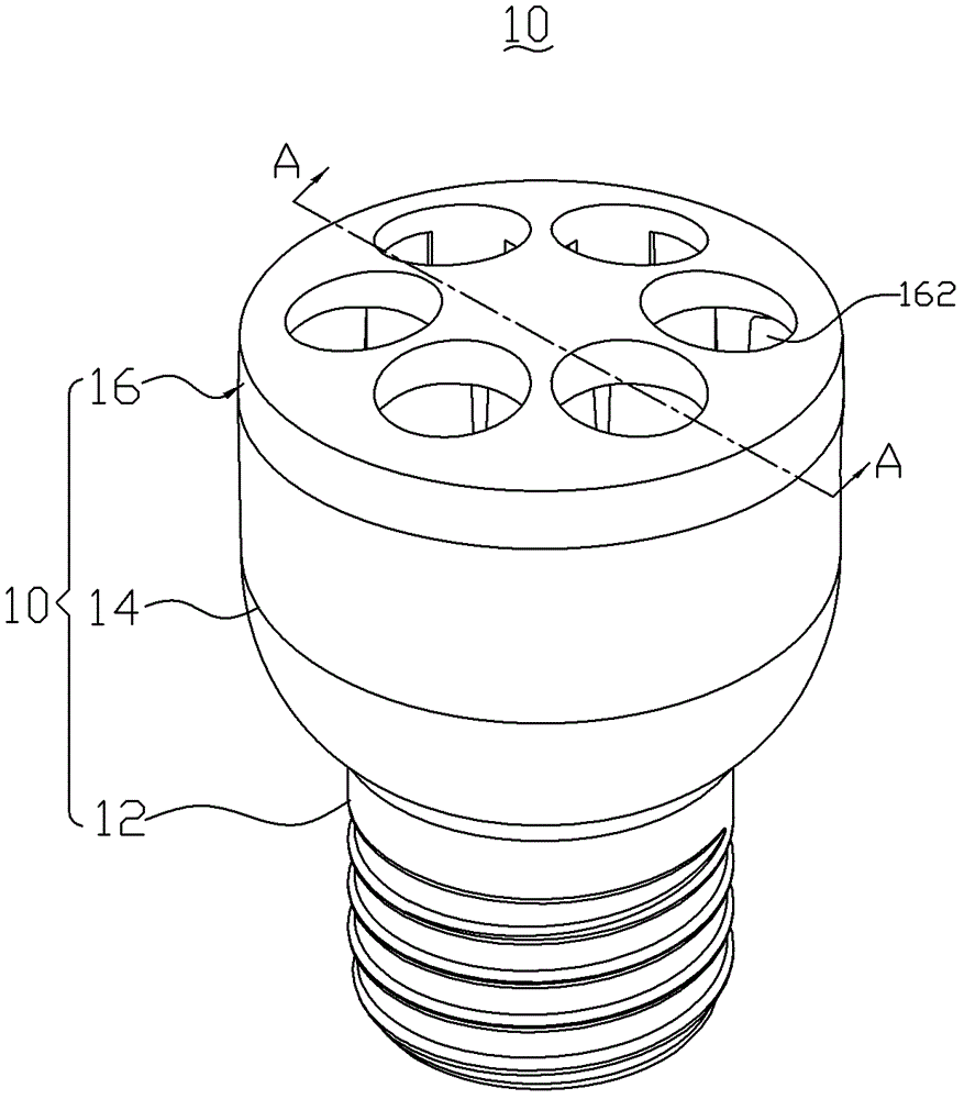
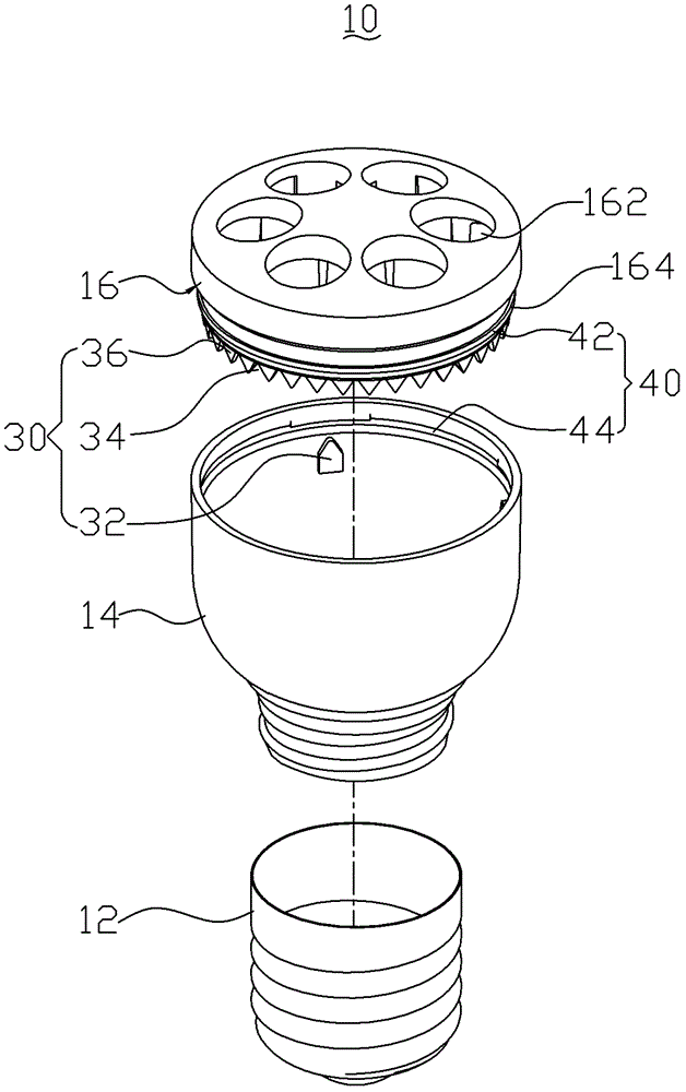
[0016] Please refer to figure 1 , The automatic assembly lamp cap 10 of the present invention comprises a lamp cap 12 , a lamp cup 14 and a mounting base 16 , the mounting base 16 , the lamp cup 14 and the lamp cap 12 are connected from top to bottom to form the lamp cap 10 . The mounting base 16 is a shell structure with a “door” shape in cross-section. The top of the mounting base 16 is provided with six mounting holes 162 , and the bottom of the mounting base 16 is provided with an annular connecting portion 164 .

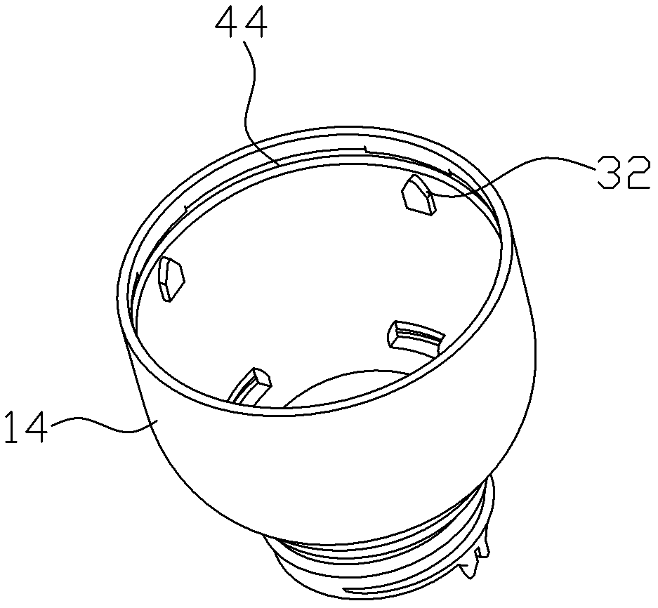
[0017] combine Figure 2 to Figure 6 As shown, the lamp cup 14 is a hollow cylindrical shell structure, and the lamp base 12 is connected to the bottom of the lamp cup 14 through threads. The lamp cup 14 is connected and fixed to the ...


PUM


Abstract

An automatically assembled lamp cap and an energy-saving lamp using the lamp cap, including a lamp cup and a mounting seat, the mounting seat is assembled on the lamp cup, and is characterized in that it also includes a radial positioning unit, and the radial positioning unit includes at least one guide block and a plurality of guide grooves, the guide block is set on the lamp cup, the guide groove is set on the mounting seat, the guide grooves are arranged at intervals in a ring shape, and the shape of the guide block is adapted to each a guide slot. The automatic assembly lamp holder and the energy-saving lamp have the advantage of realizing mechanized automatic assembly.

Description

technical field [0001] The invention relates to a lamp cap and an energy-saving lamp using the lamp cap, in particular to an automatically assembled lamp cap and an energy-saving lamp using the lamp cap. Background technique [0002] Energy-saving lamps are welcomed by consumers for their advantages of low energy consumption and high brightness. However, the existing energy-saving lamps have the problem of low assembly efficiency of the lamp caps. As disclosed on September 10, 2003, the Chinese utility model patent with the patent application number CN02269941.4 discloses a method for fastening the lamp cap assembly and the lamp tube assembly. The lamp cap assembly is provided with a card slot, and the elastic hook is used to buckle in the card slot to realize the fixed connection between the lamp cap assembly and the lamp tube assembly; although the technical solution realizes the connection between the lamp cap assembly and the lamp tube assembly, the connection method ha...

Claims


Application Information

Patent Timeline
Patent Type & Authority Patents(China)
IPC IPC(8): H01J5/56H01J5/60H01J61/36
Inventor 谢志福
Owner LEEDARSON LIGHTING XIAMEN
Learn More