
Chemical mechanical polishing device and method

A chemical machinery and grinding device technology, applied in grinding devices, grinding machine tools, grinding/polishing equipment, etc., can solve problems such as deviation, reduce chemical mechanical grinding accuracy, etc., and achieve the effect of improving accuracy

Inactive Publication Date: 2012-02-01
SEMICON MFG INT (SHANGHAI) CORP +1
View PDF7 Cites 7 Cited by
  • Summary
  • Abstract
  • Description
  • Claims
  • Application Information

AI Technical Summary

Problems solved by technology

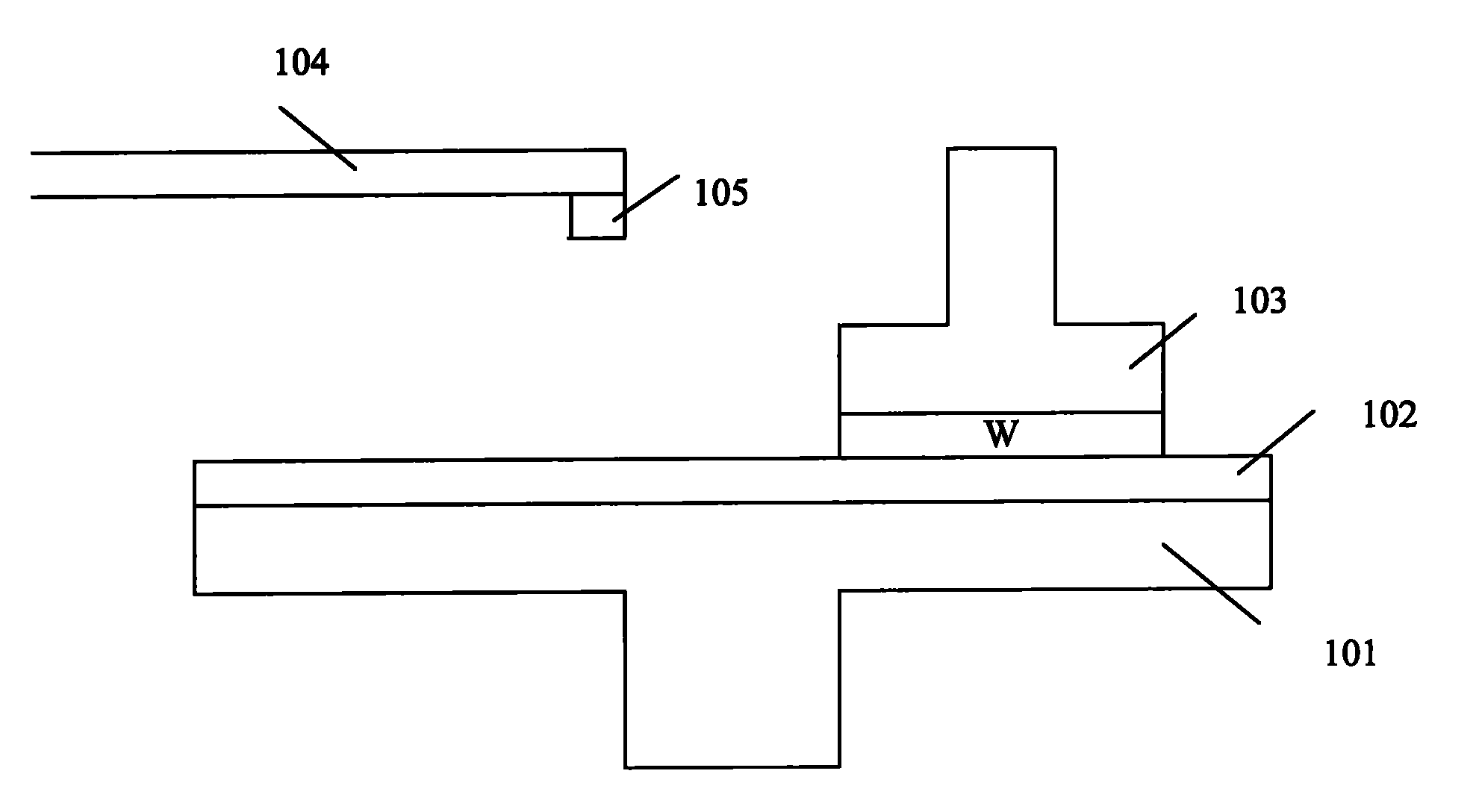
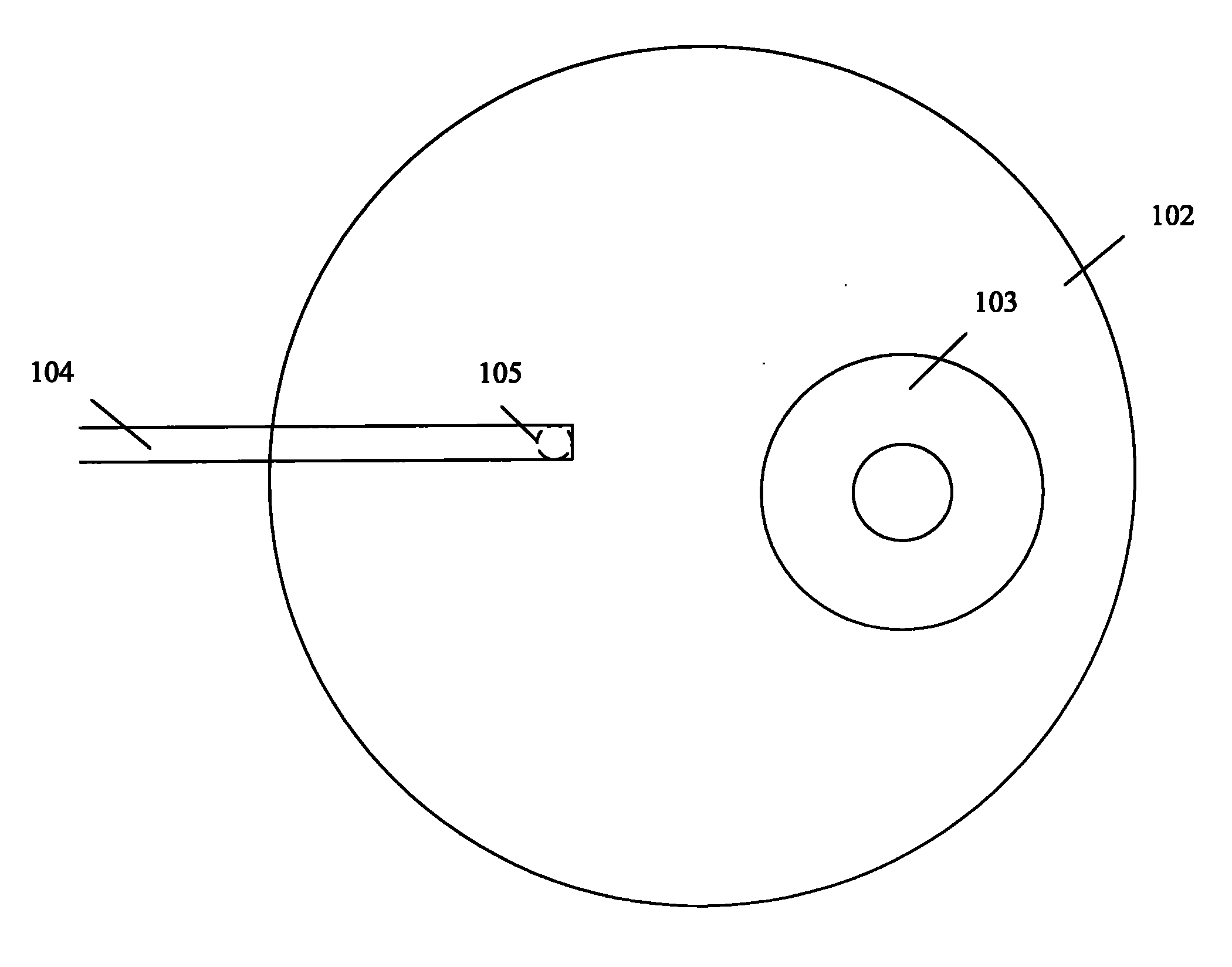
[0005] However, in practical applications, when setting the position of the grinding liquid output head 105 relative to the grinding head 103, the actual position of the grinding liquid output head 105 relative to the grinding head 103 may deviate from the ideal situation. The distribution of removal rate will also deviate from the ideal situation, which reduces the precision of chemical mechanical polishing

Method used


Image

  • Chemical mechanical polishing device and method
  • Chemical mechanical polishing device and method
  • Chemical mechanical polishing device and method

Examples


Embodiment Construction

[0027] In order to make the object, technical solution and advantages of the present invention clearer, the solutions of the present invention will be further described in detail below with reference to the accompanying drawings and examples.

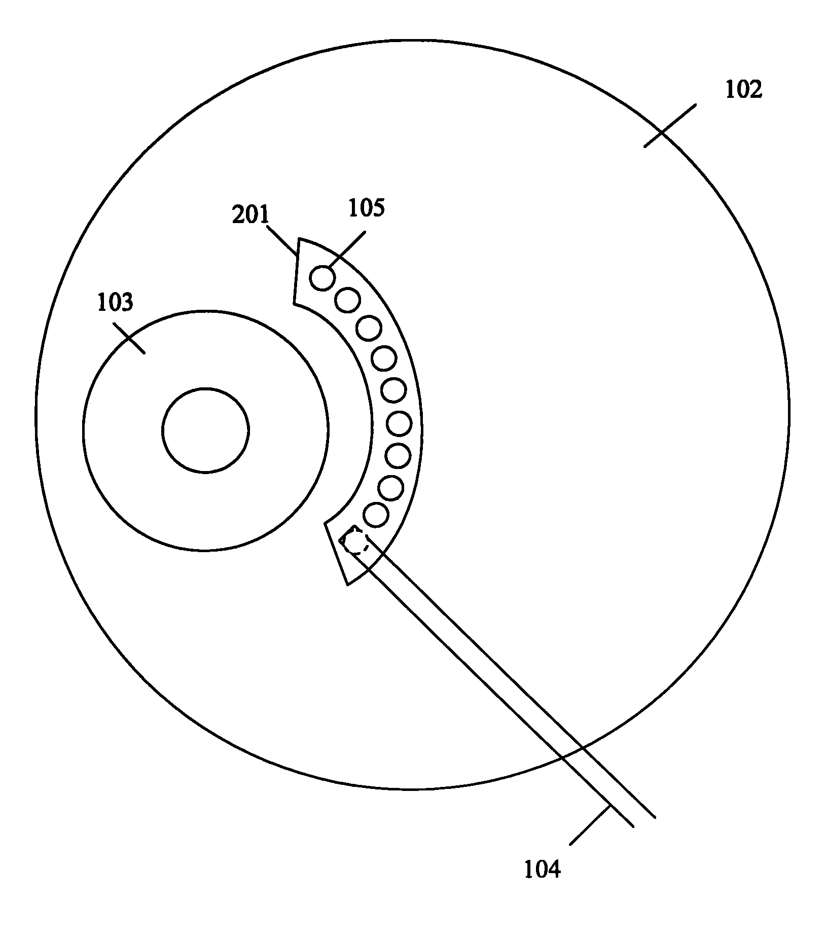
[0028] image 3 It is a top view structure diagram of an embodiment of a chemical mechanical polishing device provided by the present invention, Figure 4 It is a cross-sectional structure diagram of an embodiment of a chemical mechanical polishing device provided by the present invention. Such as image 3 and Figure 4 As shown, the device comprises: a grinding table 101, a grinding pad 102, a grinding head 103, a grinding liquid output device 201, and the grinding liquid output device 201 and the grinding head 103 are spaced at a certain distance in the horizontal direction, and the grinding liquid output device 201 is an arc shape, the arc is matched with the part of the outer circumference of the grinding head 103, and at least 2...


PUM


Abstract

The invention discloses a chemical mechanical grinding device. The device comprises a polishing head and a polishing liquid output device which are arranged at a certain interval in the horizontal direction; the polishing liquid output device is arc; the arc is matched with a part of outer circumference shape of the polishing head; and at least two polishing liquid output heads are uniformly distributed on the polishing liquid output device along the arc direction. Meanwhile, the invention also discloses a chemical mechanical polishing method; and by the device and the method, the chemical mechanical polishing accuracy can be improved.

Description

technical field [0001] The invention relates to the field of semiconductor manufacturing, in particular to a chemical mechanical grinding device and method. Background technique [0002] At present, with the wide application of electronic devices, the manufacturing process of semiconductors has been developed rapidly. In the manufacturing process of semiconductors, a chemical mechanical polishing process (CMP) is involved. figure 1 It is a cross-sectional structure diagram of a chemical mechanical polishing device in the prior art, figure 2 It is a top structural view of a chemical mechanical polishing device in the prior art. Such as figure 1 and figure 2 As shown, the device includes: a grinding table 101 , a grinding pad 102 , a grinding head 103 , a grinding liquid supply pipe 104 and a grinding liquid output head 105 . [0003] When grinding, at first the wafer W to be ground is attached to the grinding head 103, and the surface to be ground of the wafer W is cont...

Claims


Application Information

Patent Timeline
Patent Type & Authority Applications(China)
IPC IPC(8): B24B37/04B24B57/00H01L21/304
Inventor 葛军
Owner SEMICON MFG INT (SHANGHAI) CORP
Learn More